The focal length of an optical system is a measure of how strongly the system converges or diverges light; it has units of length, and for an idealized thin lens is equal to the distance between the lens and its focal points. A positive focal length indicates that a system converges light, while a negative focal length indicates that the system diverges light. A system with a shorter focal length bends the rays more sharply, bringing them to a focus in a shorter distance or diverging them more quickly. For the special case of a thin lens in air, a positive focal length is the distance over which initially collimated (parallel) rays are brought to a focus, or alternatively a negative focal length indicates how far in front of the lens a point source must be located to form a collimated beam. For more general optical systems, the focal length has no intuitive meaning; it is simply the inverse of the system's optical power.
In most photography and all telescopy, where the subject is essentially infinitely far away, longer focal length (lower optical power) leads to higher magnification and a narrower angle of view; conversely, shorter focal length or higher optical power is associated with lower magnification and a wider angle of view. On the other hand, in applications such as microscopy in which magnification is achieved by bringing the object close to the lens, a shorter focal length (higher optical power) leads to higher magnification because the subject can be brought closer to the center of projection.
Thin lens approximation
For a thin lens in air, the focal length is the distance from the center of the lens to the principal foci (or focal points) of the lens. For a converging lens (for example a convex lens), the focal length is positive and is the distance at which a beam of collimated light will be focused to a single spot. For a diverging lens (for example a concave lens), the focal length is negative and is the distance to the point from which a collimated beam appears to be diverging after passing through the lens.
When a lens is used to form an image of some object, the distance from the object to the lens u, the distance from the lens to the image v, and the focal length f are related by
The focal length of a thin convex lens can be easily measured by using it to form an image of a distant light source on a screen. The lens is moved until a sharp image is formed on the screen. In this case 1/u is negligible, and the focal length is then given by
Determining the focal length of a concave lens is somewhat more difficult. The focal length of such a lens is defined as the point at which the spreading beams of light meet when they are extended backwards. No image is formed during such a test, and the focal length must be determined by passing light (for example, the light of a laser beam) through the lens, examining how much that light becomes dispersed or bent, and following the beam of light backwards to the lens's focal point.
General optical systems
Thick lens diagram
For a thick lens (one which has a non-negligible thickness), or an imaging system consisting of several lenses or mirrors (e.g. a photographic lens or a telescope), there are several related concepts that are referred to as focal lengths:
Effective focal length (EFL)
The effective focal length is the inverse of the optical power of an optical system, and is the value used to calculate the magnification of the system.[1] The imaging properties of the optical system can be modeled by replacing the system with an ideal thin lens with the same EFL.[2] The EFL also provides a simple method for finding the nodal points without tracing any rays. It was previously called equivalent focal length (not to be confused with 35 mm-equivalent focal length).
Front focal length (FFL)
The front focal length f is the distance from the front focal point F to the front principal planeH.
Rear focal length (RFL)
The rear focal length f′ is the distance from the rear principal plane H′ to the rear focal point F′.
Front focal distance (FFD)
The front focal distance (FFD) (sF) is the distance from the front focal point of the system (F) to the vertex of the first optical surface (S1).[1][3] Some authors refer to this as "front focal length".
Back focal distance (BFD)
Back focal distance (BFD) (s′F′) is the distance from the vertex of the last optical surface of the system (S2) to the rear focal point (F′).[1][3] Some authors refer to this as "back focal length".
For an optical system in air or vacuum where the refractive index can be considered 1, the EFL, FFL, and RFL are all the same and may be called simply "focal length".
Sketch of human eye showing rear focal length f′ and EFL
For an optical system in media other than air or vacuum, the FFL and RFL are equal to the EFL times the refractive index of the medium in front of and behind the lens (n1 and n2 in the diagram above), respectively. The term "focal length" by itself is ambiguous in this case. The historical usage was to define the "focal length" as the EFL times the index of refraction of the medium.[2][4] For a system with different media on each side, such as the human eye, the front and rear focal lengths are not equal, and convention may dictate which one is called "the focal length" of the system. Some modern authors avoid this ambiguity by instead defining "focal length" to be a synonym for EFL.[1]
The distinction between front/rear focal length and EFL is important for studying the human eye. The eye can be represented by an equivalent thin lens at an air/fluid boundary with front and rear focal lengths equal to those of the eye, or it can be represented by a different equivalent thin lens that is totally in air, with focal length equal to the eye's EFL.
For the case of a lens of thickness d in air (n1 = n2 = 1), and surfaces with radii of curvatureR1 and R2, the effective focal length f is given by the Lensmaker's equation:[5]
where n is the refractive index of the lens medium. The quantity 1/f is also known as the optical power of the lens.
The corresponding front focal distance is:[6] and the back focal distance:
In the sign convention used here, the value of R1 will be positive if the first lens surface is convex, and negative if it is concave. The value of R2 is negative if the second surface is convex, and positive if concave. Sign conventions vary between different authors, which results in different forms of these equations depending on the convention used.
For a spherically-curved mirror in air, the magnitude of the focal length is equal to the radius of curvature of the mirror divided by two. The focal length is positive for a concave mirror, and negative for a convex mirror. In the sign convention used in optical design, a concave mirror has negative radius of curvature, so
where R is the radius of curvature of the mirror's surface.
An example of how lens choice affects angle of view. The photos above were taken by a 35mm camera at a fixed distance from the subject.
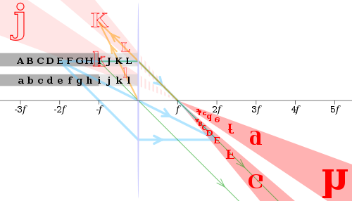
Images of black letters in a thin convex lens of focal length f are shown in red. Selected rays are shown for letters E, I and K in blue, green and orange, respectively. E (at 2f) has an equal-size, real and inverted image; I (at f) has its image at infinity; and K (at f/2) has a double-size, virtual and upright image.In this computer simulation, adjusting the field of view (by changing the focal length) while keeping the subject in frame (by changing accordingly the position of the camera) results in vastly differing images. At focal lengths approaching infinity (0 degrees of angle of view), the light rays are nearly parallel to each other, resulting in the subject looking "flattened". At small focal lengths (bigger field of view), the subject appears "foreshortened".
Camera lens focal lengths are usually specified in millimetres (mm), but some older lenses are marked in centimetres (cm) or inches.
Focal length (f) and field of view (FOV) of a lens are inversely proportional. For a standard rectilinear lens, , where x is the width of the film or imaging sensor.
When a photographic lens is set to "infinity", its rear principal plane is separated from the sensor or film, which is then situated at the focal plane, by the lens's focal length. Objects far away from the camera then produce sharp images on the sensor or film, which is also at the image plane.
To render closer objects in sharp focus, the lens must be adjusted to increase the distance between the rear principal plane and the film, to put the film at the image plane. The focal length f, the distance from the front principal plane to the object to photograph s1, and the distance from the rear principal plane to the image plane s2 are then related by:
As s1 is decreased, s2 must be increased. For example, consider a normal lens for a 35mm camera with a focal length of f = 50mm. To focus a distant object (s1 ≈ ∞), the rear principal plane of the lens must be located a distance s2 = 50mm from the film plane, so that it is at the location of the image plane. To focus an object 1m away (s1 = 1,000mm), the lens must be moved 2.6mm farther away from the film plane, to s2 = 52.6mm.
The focal length of a lens determines the magnification at which it images distant objects. It is equal to the distance between the image plane and a pinhole that images distant objects the same size as the lens in question. For rectilinear lenses (that is, with no image distortion), the imaging of distant objects is well modelled as a pinhole camera model.[7] This model leads to the simple geometric model that photographers use for computing the angle of view of a camera; in this case, the angle of view depends only on the ratio of focal length to film size. In general, the angle of view depends also on the distortion.[8]
A lens with a focal length about equal to the diagonal size of the film or sensor format is known as a normal lens; its angle of view is similar to the angle subtended by a large-enough print viewed at a typical viewing distance of the print diagonal, which therefore yields a normal perspective when viewing the print;[9] this angle of view is about 53 degrees diagonally. For full-frame 35mm-format cameras, the diagonal is 43mm and a typical "normal" lens has a 50mm focal length. A lens with a focal length shorter than normal is often referred to as a wide-angle lens (typically 35mm and less, for 35mm-format cameras), while a lens significantly longer than normal may be referred to as a telephoto lens (typically 85mm and more, for 35mm-format cameras). Technically, long focal length lenses are only "telephoto" if the focal length is longer than the physical length of the lens, but the term is often used to describe any long focal length lens.
Due to the popularity of the 35mm standard, camera–lens combinations are often described in terms of their 35mm-equivalent focal length, that is, the focal length of a lens that would have the same angle of view, or field of view, if used on a full-frame 35mm camera. Use of a 35mm-equivalent focal length is particularly common with digital cameras, which often use sensors smaller than 35mm film, and so require correspondingly shorter focal lengths to achieve a given angle of view, by a factor known as the crop factor.
Optical power
Illustration of the relationship between optical power and focal length
The main benefit of using optical power rather than focal length is that the thin lens formula has the object distance, image distance, and focal length all as reciprocals. Additionally, when relatively thin lenses are placed close together their powers approximately add. Thus, a thin 2.0-dioptre lens placed close to a thin 0.5-dioptre lens yields almost the same focal length as a single 2.5-dioptre lens.
This page is based on this Wikipedia article Text is available under the CC BY-SA 4.0 license; additional terms may apply. Images, videos and audio are available under their respective licenses.