
In geometry, a Cartesian coordinate system in a plane is a coordinate system that specifies each point uniquely by a pair of real numbers called coordinates, which are the signed distances to the point from two fixed perpendicular oriented lines, called coordinate lines, coordinate axes or just axes of the system. The point where they meet is called the origin and has (0, 0) as coordinates.
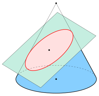
In mathematics, an ellipse is a plane curve surrounding two focal points, such that for all points on the curve, the sum of the two distances to the focal points is a constant. It generalizes a circle, which is the special type of ellipse in which the two focal points are the same. The elongation of an ellipse is measured by its eccentricity , a number ranging from to .
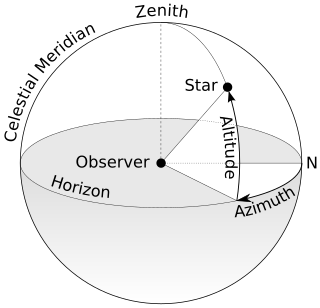
An azimuth is the angular measurement in a spherical coordinate system which represents the horizontal angle from a cardinal direction, most commonly north.

A 3D projection is a design technique used to display a three-dimensional (3D) object on a two-dimensional (2D) surface. These projections rely on visual perspective and aspect analysis to project a complex object for viewing capability on a simpler plane.

In mathematics, bilinear interpolation is a method for interpolating functions of two variables using repeated linear interpolation. It is usually applied to functions sampled on a 2D rectilinear grid, though it can be generalized to functions defined on the vertices of arbitrary convex quadrilaterals.

In geometry, a barycentric coordinate system is a coordinate system in which the location of a point is specified by reference to a simplex. The barycentric coordinates of a point can be interpreted as masses placed at the vertices of the simplex, such that the point is the center of mass of these masses. These masses can be zero or negative; they are all positive if and only if the point is inside the simplex.

In classical geometry, a radius of a circle or sphere is any of the line segments from its center to its perimeter, and in more modern usage, it is also their length. The name comes from the Latin radius, meaning ray but also the spoke of a chariot wheel. The typical abbreviation and mathematical variable name for radius is R or r. By extension, the diameter D is defined as twice the radius:
In geometry, the Hessian curve is a plane curve similar to folium of Descartes. It is named after the German mathematician Otto Hesse. This curve was suggested for application in elliptic curve cryptography, because arithmetic in this curve representation is faster and needs less memory than arithmetic in standard Weierstrass form.

In geometry, the hyperboloid model, also known as the Minkowski model after Hermann Minkowski, is a model of n-dimensional hyperbolic geometry in which points are represented by points on the forward sheet S+ of a two-sheeted hyperboloid in (n+1)-dimensional Minkowski space or by the displacement vectors from the origin to those points, and m-planes are represented by the intersections of (m+1)-planes passing through the origin in Minkowski space with S+ or by wedge products of m vectors. Hyperbolic space is embedded isometrically in Minkowski space; that is, the hyperbolic distance function is inherited from Minkowski space, analogous to the way spherical distance is inherited from Euclidean distance when the n-sphere is embedded in (n+1)-dimensional Euclidean space.
In computer vision, the motion field is an ideal representation of motion in three-dimensional space (3D) as it is projected onto a camera image. Given a simplified camera model, each point in the image is the projection of some point in the 3D scene but the position of the projection of a fixed point in space can vary with time. The motion field can formally be defined as the time derivative of the image position of all image points given that they correspond to fixed 3D points. This means that the motion field can be represented as a function which maps image coordinates to a 2-dimensional vector. The motion field is an ideal description of the projected 3D motion in the sense that it can be formally defined but in practice it is normally only possible to determine an approximation of the motion field from the image data.
In computer vision, the essential matrix is a matrix, that relates corresponding points in stereo images assuming that the cameras satisfy the pinhole camera model.

In Euclidean geometry, the intersection of a line and a line can be the empty set, a point, or another line. Distinguishing these cases and finding the intersection have uses, for example, in computer graphics, motion planning, and collision detection.
In computer vision a camera matrix or (camera) projection matrix is a matrix which describes the mapping of a pinhole camera from 3D points in the world to 2D points in an image.
The eight-point algorithm is an algorithm used in computer vision to estimate the essential matrix or the fundamental matrix related to a stereo camera pair from a set of corresponding image points. It was introduced by Christopher Longuet-Higgins in 1981 for the case of the essential matrix. In theory, this algorithm can be used also for the fundamental matrix, but in practice the normalized eight-point algorithm, described by Richard Hartley in 1997, is better suited for this case.
In computer vision, triangulation refers to the process of determining a point in 3D space given its projections onto two, or more, images. In order to solve this problem it is necessary to know the parameters of the camera projection function from 3D to 2D for the cameras involved, in the simplest case represented by the camera matrices. Triangulation is sometimes also referred to as reconstruction or intersection.
Computer stereo vision is the extraction of 3D information from digital images, such as those obtained by a CCD camera. By comparing information about a scene from two vantage points, 3D information can be extracted by examining the relative positions of objects in the two panels. This is similar to the biological process of stereopsis.
In mathematics, the Jacobi curve is a representation of an elliptic curve different from the usual one defined by the Weierstrass equation. Sometimes it is used in cryptography instead of the Weierstrass form because it can provide a defence against simple and differential power analysis style (SPA) attacks; it is possible, indeed, to use the general addition formula also for doubling a point on an elliptic curve of this form: in this way the two operations become indistinguishable from some side-channel information. The Jacobi curve also offers faster arithmetic compared to the Weierstrass curve.
In mathematics, the Montgomery curve is a form of elliptic curve introduced by Peter L. Montgomery in 1987, different from the usual Weierstrass form. It is used for certain computations, and in particular in different cryptography applications.

In algebraic geometry, the twisted Edwards curves are plane models of elliptic curves, a generalisation of Edwards curves introduced by Bernstein, Birkner, Joye, Lange and Peters in 2008. The curve set is named after mathematician Harold M. Edwards. Elliptic curves are important in public key cryptography and twisted Edwards curves are at the heart of an electronic signature scheme called EdDSA that offers high performance while avoiding security problems that have surfaced in other digital signature schemes.

In geometry, an intersection is a point, line, or curve common to two or more objects. The simplest case in Euclidean geometry is the line–line intersection between two distinct lines, which either is one point or does not exist. Other types of geometric intersection include:


