In physics, ray tracing is a method for calculating the path of waves or particles through a system with regions of varying propagation velocity, absorption characteristics, and reflecting surfaces. Under these circumstances, wavefronts may bend, change direction, or reflect off surfaces, complicating analysis.
Historically, ray tracing involved analytic solutions to the ray's trajectories. In modern applied physics and engineering physics, the term also encompasses numerical solutions to the Eikonal equation. For example, ray-marching involves repeatedly advancing idealized narrow beams called rays through the medium by discrete amounts. Simple problems can be analyzed by propagating a few rays using simple mathematics. More detailed analysis can be performed by using a computer to propagate many rays.
Ray tracing of a beam of light passing through a medium with changing refractive index. The ray is advanced by a small amount, and then the direction is re-calculated.
Ray tracing works by assuming that the particle or wave can be modeled as a large number of very narrow beams (rays), and that there exists some distance, possibly very small, over which such a ray is locally straight. The ray tracer will advance the ray over this distance, and then use a local derivative of the medium to calculate the ray's new direction. From this location, a new ray is sent out and the process is repeated until a complete path is generated. If the simulation includes solid objects, the ray may be tested for intersection with them at each step, making adjustments to the ray's direction if a collision is found. Other properties of the ray may be altered as the simulation advances as well, such as intensity, wavelength, or polarization. This process is repeated with as many rays as are necessary to understand the behavior of the system.
Ray tracing is being increasingly used in astronomy to simulate realistic images of the sky. Unlike conventional simulations, ray tracing does not use the expected or calculated point spread function (PSF) of a telescope and instead traces the journey of each photon from entrance in the upper atmosphere to collision with the detector.[1] Most of the dispersion and distortion, arising mainly from atmosphere, optics and detector are taken into account. While this method of simulating images is inherently slow, advances in CPU and GPU capabilities has somewhat mitigated this problem. It can also be used in designing telescopes. Notable examples include Large Synoptic Survey Telescope where this kind of ray tracing was first used with PhoSim[2] to create simulated images.[3]
Radio signals traced from the transmitter at the left to the receiver at the right (triangles on the base of the 3D grid)
One particular form of ray tracing is radio signal ray tracing, which traces radio signals, modeled as rays, through the ionosphere where they are refracted and/or reflected back to the Earth. This form of ray tracing involves the integration of differential equations that describe the propagation of electromagnetic waves through dispersive and anisotropic media such as the ionosphere. An example of physics-based radio signal ray tracing is shown to the right. Radio communicators use ray tracing to help determine the precise behavior of radio signals as they propagate through the ionosphere.
The image at the right illustrates the complexity of the situation. Unlike optical ray tracing where the medium between objects typically has a constant refractive index, signal ray tracing must deal with the complexities of a spatially varying refractive index, where changes in ionospheric electron densities influence the refractive index and hence, ray trajectories. Two sets of signals are broadcast at two different elevation angles. When the main signal penetrates into the ionosphere, the magnetic field splits the signal into two component waves which are separately ray traced through the ionosphere. The ordinary wave (red) component follows a path completely independent of the extraordinary wave (green) component.
Sound velocity in the ocean varies with depth due to changes in density and temperature, reaching a local minimum near a depth of 800–1000 meters. This local minimum, called the SOFAR channel, acts as a waveguide, as sound tends to bend towards it. Ray tracing may be used to calculate the path of sound through the ocean up to very large distances, incorporating the effects of the SOFAR channel, as well as reflections and refractions off the ocean surface and bottom. From this, locations of high and low signal intensity may be computed, which are useful in the fields of ocean acoustics, underwater acoustic communication, and acoustic thermometry.
A ray tracing of acoustic wavefronts propagating through the varying density of the ocean. The path can be seen to oscillate about the SOFAR channel.
Ray tracing may be used in the design of lenses and optical systems, such as in cameras, microscopes, telescopes, and binoculars, and its application in this field dates back to the 1900s. Geometric ray tracing is used to describe the propagation of light rays through a lens system or optical instrument, allowing the image-forming properties of the system to be modelled. The following effects can be integrated into a ray tracer in a straightforward fashion:
For the application of lens design, two special cases of wave interference are important to account for. In a focal point, rays from a point light source meet again and may constructively or destructively interfere with each other. Within a very small region near this point, incoming light may be approximated by plane waves which inherit their direction from the rays. The optical path length from the light source is used to compute the phase. The derivative of the position of the ray in the focal region on the source position is used to obtain the width of the ray, and from that the amplitude of the plane wave. The result is the point spread function, whose Fourier transform is the optical transfer function. From this, the Strehl ratio can also be calculated.
The other special case to consider is that of the interference of wavefronts, which are approximated as planes. However, when the rays come close together or even cross, the wavefront approximation breaks down. Interference of spherical waves is usually not combined with ray tracing, thus diffraction at an aperture cannot be calculated. However, these limitations can be resolved by an advanced modeling technique called field tracing. Field tracing is a modelling technique, combining geometric optics with physical optics enabling to overcome the limitations of interference and diffraction in designing.
The ray tracing techniques are used to optimize the design of the instrument by minimizing aberrations, for photography, and for longer wavelength applications such as designing microwave or even radio systems, and for shorter wavelengths, such as ultraviolet and X-ray optics.
Before the advent of the computer, ray tracing calculations were performed by hand using trigonometry and logarithmic tables. The optical formulas of many classic photographic lenses were optimized by roomfuls of people, each of whom handled a small part of the large calculation. Now they are worked out in optical design software. A simple version of ray tracing known as ray transfer matrix analysis is often used in the design of optical resonators used in lasers. The basic principles of the most frequently used algorithm could be found in Spencer and Murty's fundamental paper: "General ray tracing Procedure".[4]
Focal-plane ray tracing
FF and BF as on-axis points of the front and back (or rear) focal planes of the lens
There is a ray tracing technique called focal-plane ray tracing where how an optical ray will be after a lens is determined based on a lens focal plane and how the ray crosses the plane.[5] This method utilizes the fact that rays from a point on the front focal plane of a positive lens will be parallel right after the lens and rays toward a point on the back or rear focal plane of a negative lens will also be parallel after the lens. In each case, the direction of the parallel rays after the lens is determined by a ray appearing to cross the lens nodal points (or the lens center for a thin lens).
FF and BF as on-axis points of the front and back (or rear) focal planes of the lens
Seismology
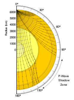
This ray tracing of seismic waves through the interior of the Earth shows that paths can be quite complicated, and reveals telling information about the structure of our planet.
In seismology, geophysicists use ray tracing to aid in earthquake location and tomographic reconstruction of the Earth's interior.[6][7]Seismic wave velocity varies within and beneath Earth's crust, causing these waves to bend and reflect. Ray tracing may be used to compute paths through a geophysical model, following them back to their source, such as an earthquake, or deducing the properties of the intervening material.[8] In particular, the discovery of the seismic shadow zone (illustrated at right) allowed scientists to deduce the presence of Earth's molten core.
General relativity
In general relativity, where gravitational lensing can occur, the geodesics of the light rays receiving at the observer are integrated backwards in time until they hit the region of interest. Image synthesis under this technique can be view as an extension of the usual ray tracing in computer graphics.[9][10] An example of such synthesis is found in the 2014 film Interstellar.[11]
In laser-plasma physics ray-tracing can be used to simplify the calculations of laser propagation inside a plasma. Analytic solutions for ray trajectories in simple plasma density profiles are a well established,[12] however researchers in laser-plasma physics often rely on ray-marching techniques due to the complexity of plasma density, temperature, and flow profiles which are often solved for using computational fluid dynamics simulations.
This page is based on this Wikipedia article Text is available under the CC BY-SA 4.0 license; additional terms may apply. Images, videos and audio are available under their respective licenses.