Gouraud shading, named after Henri Gouraud, is an interpolation method used in computer graphics to produce continuous shading of surfaces represented by polygon meshes. In practice, Gouraud shading is most often used to achieve continuous lighting on triangle meshes by computing the lighting at the corners of each triangle and linearly interpolating the resulting colours for each pixel covered by the triangle. Gouraud first published the technique in 1971. However, enhanced hardware support for superior shading models has yielded Gouraud shading largely obsolete in modern rendering.

Texture mapping is a method for mapping a texture on a computer-generated graphic. "Texture" in this context can be high frequency detail, surface texture, or color.
The Phong reflection model is an empirical model of the local illumination of points on a surface designed by the computer graphics researcher Bui Tuong Phong. In 3D computer graphics, it is sometimes referred to as "Phong shading", particularly if the model is used with the interpolation method of the same name and in the context of pixel shaders or other places where a lighting calculation can be referred to as “shading”.
In 3D computer graphics, Phong shading, Phong interpolation, or normal-vector interpolation shading is an interpolation technique for surface shading invented by computer graphics pioneer Bui Tuong Phong. Phong shading interpolates surface normals across rasterized polygons and computes pixel colors based on the interpolated normals and a reflection model. Phong shading may also refer to the specific combination of Phong interpolation and the Phong reflection model.

Shading refers to the depiction of depth perception in 3D models or illustrations by varying the level of darkness. Shading tries to approximate local behavior of light on the object's surface and is not to be confused with techniques of adding shadows, such as shadow mapping or shadow volumes, which fall under global behavior of light.

In 3D computer graphics, normal mapping, or Dot3 bump mapping, is a texture mapping technique used for faking the lighting of bumps and dents – an implementation of bump mapping. It is used to add details without using more polygons. A common use of this technique is to greatly enhance the appearance and details of a low polygon model by generating a normal map from a high polygon model or height map.

In 3D computer graphics and solid modeling, a polygon mesh is a collection of vertices, edges and faces that defines the shape of a polyhedral object's surface. It simplifies rendering, as in a wire-frame model. The faces usually consist of triangles, quadrilaterals (quads), or other simple convex polygons (n-gons). A polygonal mesh may also be more generally composed of concave polygons, or even polygons with holes.

In computer graphics, a shader is a computer program that calculates the appropriate levels of light, darkness, and color during the rendering of a 3D scene—a process known as shading. Shaders have evolved to perform a variety of specialized functions in computer graphics special effects and video post-processing, as well as general-purpose computing on graphics processing units.

A lightmap is a data structure used in lightmapping, a form of surface caching in which the brightness of surfaces in a virtual scene is pre-calculated and stored in texture maps for later use. Lightmaps are most commonly applied to static objects in applications that use real-time 3D computer graphics, such as video games, in order to provide lighting effects such as global illumination at a relatively low computational cost.
The computer graphics pipeline, also known as the rendering pipeline, or graphics pipeline, is a framework within computer graphics that outlines the necessary procedures for transforming a three-dimensional (3D) scene into a two-dimensional (2D) representation on a screen. Once a 3D model is generated, the graphics pipeline converts the model into a visually perceivable format on the computer display. Due to the dependence on specific software, hardware configurations, and desired display attributes, a universally applicable graphics pipeline does not exist. Nevertheless, graphics application programming interfaces (APIs), such as Direct3D, OpenGL and Vulkan were developed to standardize common procedures and oversee the graphics pipeline of a given hardware accelerator. These APIs provide an abstraction layer over the underlying hardware, relieving programmers from the need to write code explicitly targeting various graphics hardware accelerators like AMD, Intel, Nvidia, and others.
OBJ is a geometry definition file format first developed by Wavefront Technologies for its Advanced Visualizer animation package. The file format is open and has been adopted by other 3D graphics application vendors.
In 3D computer graphics, polygonal modeling is an approach for modeling objects by representing or approximating their surfaces using polygon meshes. Polygonal modeling is well suited to scanline rendering and is therefore the method of choice for real-time computer graphics. Alternate methods of representing 3D objects include NURBS surfaces, subdivision surfaces, and equation-based representations used in ray tracers.

STL is a file format native to the stereolithography CAD software created by 3D Systems. Chuck Hull, the inventor of stereolithography and 3D Systems’ founder, reports that the file extension is an abbreviation for stereolithography, although it is also referred to as standard triangle language or standard tessellation language.
In computer graphics, per-pixel lighting refers to any technique for lighting an image or scene that calculates illumination for each pixel on a rendered image. This is in contrast to other popular methods of lighting such as vertex lighting, which calculates illumination at each vertex of a 3D model and then interpolates the resulting values over the model's faces to calculate the final per-pixel color values.
The Blinn–Phong reflection model, also called the modified Phong reflection model, is a modification developed by Jim Blinn to the Phong reflection model.
Computer graphics lighting is the collection of techniques used to simulate light in computer graphics scenes. While lighting techniques offer flexibility in the level of detail and functionality available, they also operate at different levels of computational demand and complexity. Graphics artists can choose from a variety of light sources, models, shading techniques, and effects to suit the needs of each application.
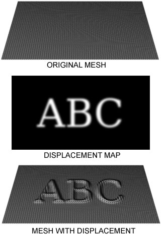
Displacement mapping is an alternative computer graphics technique in contrast to bump, normal, and parallax mapping, using a texture or height map to cause an effect where the actual geometric position of points over the textured surface are displaced, often along the local surface normal, according to the value the texture function evaluates to at each point on the surface. It gives surfaces a great sense of depth and detail, permitting in particular self-occlusion, self-shadowing and silhouettes; on the other hand, it is the most costly of this class of techniques owing to the large amount of additional geometry.
Additive manufacturing file format (AMF) is an open standard for describing objects for additive manufacturing processes such as 3D printing. The official ISO/ASTM 52915:2016 standard is an XML-based format designed to allow any computer-aided design software to describe the shape and composition of any 3D object to be fabricated on any 3D printer via a computer-aided manufacturing software. Unlike its predecessor STL format, AMF has native support for color, materials, lattices, and constellations.

In computer graphics, tessellation is the dividing of datasets of polygons presenting objects in a scene into suitable structures for rendering. Especially for real-time rendering, data is tessellated into triangles, for example in OpenGL 4.0 and Direct3D 11.
This is a glossary of terms relating to computer graphics.