
Spot welding is a type of electric resistance welding used to weld various sheet metal products, through a process in which contacting metal surface points are joined by the heat obtained from resistance to electric current.
Induction welding is a form of welding that uses electromagnetic induction to heat the workpiece. The welding apparatus contains an induction coil that is energised with a radio-frequency electric current. This generates a high-frequency electromagnetic field that acts on either an electrically conductive or a ferromagnetic workpiece. In an electrically conductive workpiece, the main heating effect is resistive heating, which is due to induced currents called eddy currents. In a ferromagnetic workpiece, the heating is caused mainly by hysteresis, as the electromagnetic field repeatedly distorts the magnetic domains of the ferromagnetic material. In practice, most materials undergo a combination of these two effects.

Induction heating is the process of heating electrically conductive materials, namely metals or semi-conductors, by electromagnetic induction, through heat transfer passing through an inductor that creates an electromagnetic field within the coil to heat up and possibly melt steel, copper, brass, graphite, gold, silver, aluminum, or carbide.

Ultrasonic welding is an industrial process whereby high-frequency ultrasonic acoustic vibrations are locally applied to work pieces being held together under pressure to create a solid-state weld. It is commonly used for plastics and metals, and especially for joining dissimilar materials. In ultrasonic welding, there are no connective bolts, nails, soldering materials, or adhesives necessary to bind the materials together. When used to join metals, the temperature stays well below the melting point of the involved materials, preventing any unwanted properties which may arise from high temperature exposure of the metal.

Plastic welding is welding for semi-finished plastic materials, and is described in ISO 472 as a process of uniting softened surfaces of materials, generally with the aid of heat. Welding of thermoplastics is accomplished in three sequential stages, namely surface preparation, application of heat and pressure, and cooling. Numerous welding methods have been developed for the joining of semi-finished plastic materials. Based on the mechanism of heat generation at the welding interface, welding methods for thermoplastics can be classified as external and internal heating methods, as shown in Fig 1.
Friction welding (FWR) is a solid-state welding and bonding process that generates heat through mechanical friction between workpieces in relative motion to one another. The process is used with the addition of a lateral force called "upset" to plastically displace and fuse the materials. Friction welding is a solid-state welding technique similar to forge welding. Instead of a fusion welding process, Friction welding is used with metals and thermoplastics in a wide variety of aviation and automotive applications.

Plasma arc welding (PAW) is an arc welding process similar to gas tungsten arc welding (GTAW). The electric arc is formed between an electrode and the workpiece. The key difference from GTAW is that in PAW, the electrode is positioned within the body of the torch, so the plasma arc is separated from the shielding gas envelope. The plasma is then forced through a fine-bore copper nozzle which constricts the arc and the plasma exits the orifice at high velocities and a temperature approaching 28,000 °C (50,000 °F) or higher.

Friction stir welding (FSW) is a solid-state joining process that uses a non-consumable tool to join two facing workpieces without melting the workpiece material. Heat is generated by friction between the rotating tool and the workpiece material, which leads to a softened region near the FSW tool. While the tool is traversed along the joint line, it mechanically intermixes the two pieces of metal, and forges the hot and softened metal by the mechanical pressure, which is applied by the tool, much like joining clay, or dough. It is primarily used on wrought or extruded aluminium and particularly for structures which need very high weld strength. FSW is capable of joining aluminium alloys, copper alloys, titanium alloys, mild steel, stainless steel and magnesium alloys. More recently, it was successfully used in welding of polymers. In addition, joining of dissimilar metals, such as aluminium to magnesium alloys, has been recently achieved by FSW. Application of FSW can be found in modern shipbuilding, trains, and aerospace applications.
Electric resistance welding (ERW) is a welding process in which metal parts in contact are permanently joined by heating them with an electric current, melting the metal at the joint. Electric resistance welding is widely used, for example, in manufacture of steel pipe and in assembly of bodies for automobiles. The electric current can be supplied to electrodes that also apply clamping pressure, or may be induced by an external magnetic field. The electric resistance welding process can be further classified by the geometry of the weld and the method of applying pressure to the joint: spot welding, seam welding, flash welding, projection welding, for example. Some factors influencing heat or welding temperatures are the proportions of the workpieces, the metal coating or the lack of coating, the electrode materials, electrode geometry, electrode pressing force, electric current and length of welding time. Small pools of molten metal are formed at the point of most electrical resistance as an electric current is passed through the metal. In general, resistance welding methods are efficient and cause little pollution, but their applications are limited to relatively thin materials.

A heat sealer is a machine used to seal products, packaging, and other thermoplastic materials using heat. This can be with uniform thermoplastic monolayers or with materials having several layers, at least one being thermoplastic. Heat sealing can join two similar materials together or can join dissimilar materials, one of which has a thermoplastic layer.
Electrogas welding (EGW) is a continuous vertical-position arc welding process developed in 1961 in which an arc is struck between a consumable electrode and the workpiece. A shielding gas is sometimes used, but pressure is not applied. A major difference between EGW and its cousin, electroslag welding, is that the arc in EGW is not extinguished but instead remains struck throughout the welding process. It is used to make square-groove welds for butt and t-joints, especially in the shipbuilding industry and in the construction of storage tanks.
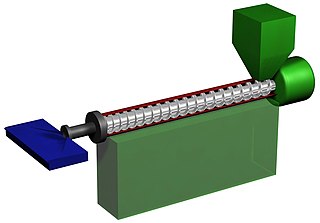
Plastics extrusion is a high-volume manufacturing process in which raw plastic is melted and formed into a continuous profile. Extrusion produces items such as pipe/tubing, weatherstripping, fencing, deck railings, window frames, plastic films and sheeting, thermoplastic coatings, and wire insulation.
Hot plate welding, also called heated tool welding, is a thermal welding technique for joining thermoplastics. A heated tool is placed against or near the two surfaces to be joined in order to melt them. Then, the heat source is removed, and the surfaces are brought together under pressure. Hot plate welding has relatively long cycle times, ranging from 10 seconds to minutes, compared to vibration or ultrasonic welding. However, its simplicity and ability to produce strong joints in almost all thermoplastics make it widely used in mass production and for large structures, like large-diameter plastic pipes. Different inspection techniques are implemented in order to identify various discontinuities or cracks.
Laser welding of polymers is a set of methods used to join polymeric components through the use of a laser. It can be performed using CO2 lasers, Nd:YAG lasers, Diode lasers and Fiber lasers.
Spin welding is a form of friction welding used to join thermoplastic parts. The parts to be welded must be round, and in plane with each other. Like all other welding methods this process utilizes heat, time, and pressure to create a weld joint. Heat is generated via internal friction generated between the two parts when rotating and subjected to a load normal to the weld joint. This frictional heat causes the plastic to melt and a bond to be created.
Extrusion welding is one of the processes used to weld thermoplastics and composites, developed in the 1960s as an evolution of hot gas welding. It can be a manual or automated process.
Ultrasonic welding is a method of joining thermoplastic components by heating and subsequent melting of surfaces in contact. Mechanical vibration with frequency between 10 and 70 kHz and amplitude of 10 to 250 μm is applied to joining parts. After ultrasonic energy is turned off, the parts remain in contact under pressure for some time while the melt layer cools down creating a weld.
Advanced thermoplastic composites (ACM) have a high strength fibres held together by a thermoplastic matrix. Advanced thermoplastic composites are becoming more widely used in the aerospace, marine, automotive and energy industry. This is due to the decreasing cost and superior strength to weight ratios, over metallic parts. Advance thermoplastic composite have excellent damage tolerance, corrosion resistant, high fracture toughness, high impact resistance, good fatigue resistance, low storage cost, and infinite shelf life. Thermoplastic composites also have the ability to be formed and reformed, repaired and fusion welded.
Radio-frequency welding, also known as dielectric welding and high-frequency welding, is a plastic welding process that utilizes high-frequency electric fields to induce heating and melting of thermoplastic base materials. The electric field is applied by a pair of electrodes after the parts being joined are clamped together. The clamping force is maintained until the joint solidifies. Advantages of this process are fast cycle times, automation, repeatability, and good weld appearance. Only plastics which have dipoles can be heated using radio waves and therefore not all plastics are able to be welded using this process. Also, this process is not well suited for thick or overly complex joints. The most common use of this process is lap joints or seals on thin plastic sheets or parts.
Implant induction welding is a joining method used in plastic manufacturing. The welding process uses an induction coil to excite and heat electromagnetically susceptible material at the joint interface and melt the thermoplastic. The susceptible material can be contained in a gasket placed between the welding surface, or within the actual components of a composite material. Its usage is common for large, unusually shaped, or delicate parts that would be difficult to weld through other methods.
