Location where metal or plastic workpieces are joined together
Welding joint
In metalworking, a welding joint is a point or edge where two or more pieces of metal or plastic are joined together. They are formed by welding two or more workpieces according to a particular geometry. There are five types of joints referred to by the American Welding Society: butt, corner, edge, lap, and tee. These types may have various configurations at the joint where actual welding can occur.
Butt welds are welds where two pieces of metal to be joined are in the same plane.[1] These welds require only some preparation and are used with thin sheet metals that can be welded with a single pass.[2] Common issues that can weaken a butt weld are the entrapment of slag, excessive porosity, or cracking. For strong welds, the goal is to use the least amount of welding material possible. Butt welds are prevalent in automated welding processes, such as submerged-arc welding, due to their relative ease of preparation.[3] When metals are welded without human guidance, there is no operator to adjust non-ideal joint preparation. Because of this necessity, butt welds can be utilized for their simplistic design to be fed through automated welding machines efficiently.
Types
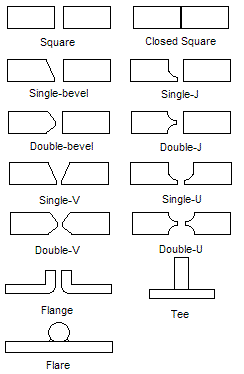
Butt joint geometries
There are many types of butt welds, but all fall within one of these categories: single-welded butt joints, double-welded butt joint, and open or closed butt joints. A single welded butt joint is the name for a joint that has only been welded from one side. A double-welded butt joint is created when the weld has been welded from both sides. With double welding, the depths of each weld can vary slightly. A closed weld is a type of joint in which the two pieces that will be joined are touching during the welding process. An open weld is the joint type where the two pieces have a small gap in between them during the welding process.
Square butt joints
The square groove is a butt welding joint with the two pieces being flat and parallel to each other. This joint is simple to prepare, economical to use, and provides satisfactory strength but is limited by joint thickness. The closed square butt weld is a type of square-groove joint with no spacing in between the pieces. This joint type is common with gas and arc welding. For thicker joints, the edge of each member of the joint must be prepared to a particular geometry to provide accessibility for welding and to ensure the desired weld soundness and strength. The opening or gap at the root of the joint and the included angle of the groove should be selected to require the least weld metal necessary to give needed access and meet strength requirements. Only metal up to 4.5mm thick is usually used for square butt joints.
V-joints
Single V welds are similar to a bevel joint, but instead of only one side having the bevelled edge, both sides of the weld joint are beveled. In thick metals, and when welding can be performed from both sides of the work piece, a double-V joint is used. When welding thicker metals, a double-V joint requires less filler material because there are two narrower V-joints compared to a wider single-V joint. Also the double-V joint helps compensate for warping forces. With a single-V joint, stress tends to warp the piece in one direction when the V-joint is filled, but with a double-V-joint, there are welds on both sides of the material, having opposing stresses, straightening the material.
J-joints
Single-J butt welds are when one piece of the weld is shaped like a J that easily accepts filler material and the other piece is square. A J-groove is formed either with special cutting machinery or by grinding the joint edge into the form of a J. Although a J-groove is more difficult and costly to prepare than a V-groove, a single J-groove on metal between a half an inch and three-quarters of an inch thick provides a stronger weld that requires less filler material. Double-J butt welds have one piece that has a J shape from both directions and the other piece is square.
U-joints
Single-U butt welds are welds that have both edges of the weld surface shaped like a J, but once they come together, they form a U. Double-U joints have a U formation on both the top and bottom of the prepared joint. U-joints are the most expensive edge to prepare and weld. They are usually used on thick base metals where a V-groove would be at such an extreme angle that it would cost too much to fill.
Tee-Joints
The Tee Weld Joint is formed when two bars or sheets are joined perpendicular to each other in the form of a T shape. This weld is made from the resistance butt welding process. It can also be performed by Extrusion Welding. Usually two flat pieces of poly are welded at 90 degrees to each other, and extrusion welded on both sides.
Others
Thin sheet metals are often flanged to produce edge-flange or corner-flange welds. These welds are typically made without the addition of filler metal because the flange melts and provides all the filler needed. Pipes and tubing can be made from rolling and welding together strips, sheets, or plates of material.[4]
Flare-groove joints are used for welding metals that, because of their shape, form a convenient groove for welding, such as a pipe against a flat surface.
Selection of the right weld joint depends on the thickness and process used. The square welds are the most economical for pieces thinner than 3/8”, because they don’t require the edge to be prepared.[5] Double-groove welds are the most economical for thicker pieces because they require less weld material and time. The use of fusion welding is common for closed single-bevel, closed single J, open single J, and closed double J butt joints. The use of gas and arc welding is ideal for double-bevel, closed double-bevel, open double-bevel, single-bevel, and open single-bevel butt welds.
Below are listed ideal joint thicknesses for the various types of butt. When the thickness of a butt weld is defined it is measured at the thinner part and does not compensate for the weld reinforcement.
Diagram of a cruciform joint between 3 plates of metal
A cruciform joint is a specific joint in which four spaces are created by the welding of three plates of metal at right angles. Cruciform joints suffer fatigue when subjected to continuously varying loads.[6]
In the American Bureau of Shipping Rules for Steel Vessels, cruciform joints may be considered a double barrier if the two substances requiring a double barrier are in opposite corners diagonally. Double barriers are often required to separate oil and seawater, chemicals and potable water, etc.[7]
Plate edge preparation
In common welding practices, the welding surface must be prepared to ensure the strongest weld possible. Preparation is needed for all forms of welding and all types of joints. Generally, butt welds require very little preparation, but some is still needed for the best results. Plate edges can be prepared for butt joints in various ways, but the five most common techniques are oxyacetylene cutting (oxy-fuel welding and cutting), machining, chipping, grinding, and air carbon-arc cutting or gouging. Each technique has unique advantages to their use.
For steel materials, oxyacetylene cutting is the most common form of preparation. This technique is advantageous because of its speed, low cost, and adaptability. Machining is the most effective for reproducibility and mass production of parts. The preparation of J or U joints is commonly prepared by machining due to the need for high accuracy. The chipping method is used to prepare parts that were produced by casting. The use of grinding to prepare pieces is reserved for small sections that cannot be prepared by other methods. Air carbon arc cutting is common in industries that work with stainless steels, cast iron, or ordinary carbon steel.[8]
Prior to welding dissimilar materials, one or both faces of the groove can be buttered. The buttered layer can be the same alloy as the filler metal or a different filler metal that will act as a buffer between the two metals to be joined.
This page is based on this Wikipedia article Text is available under the CC BY-SA 4.0 license; additional terms may apply. Images, videos and audio are available under their respective licenses.