Sutton SignWriting, or simply SignWriting, is a system of writing sign languages. It is highly featural and visually iconic, both in the shapes of the characters, which are abstract pictures of the hands, face, and body, and in their spatial arrangement on the page, which does not follow a sequential order like the letters that make up written English words. It was developed in 1974 by Valerie Sutton, a dancer who had, two years earlier, developed DanceWriting. Some newer standardized forms are known as the International Sign Writing Alphabet (ISWA).

A triangle is a polygon with three edges and three vertices. It is one of the basic shapes in geometry. A triangle with vertices A, B, and C is denoted .

In geometry, two figures or objects are congruent if they have the same shape and size, or if one has the same shape and size as the mirror image of the other.

A right triangle or right-angled triangle (British), or more formally an orthogonal triangle, formerly called a rectangled triangle, is a triangle in which one angle is a right angle, i.e., in which two sides are perpendicular. The relation between the sides and other angles of the right triangle is the basis for trigonometry.

In geometry and trigonometry, a right angle is an angle of exactly 90 degrees or /2 radians corresponding to a quarter turn. If a ray is placed so that its endpoint is on a line and the adjacent angles are equal, then they are right angles. The term is a calque of Latin angulus rectus; here rectus means "upright", referring to the vertical perpendicular to a horizontal base line.

Shielded metal arc welding (SMAW), also known as manual metal arc welding, flux shielded arc welding or informally as stick welding, is a manual arc welding process that uses a consumable electrode covered with a flux to lay the weld.

In geometry, a hypotenuse is the longest side of a right-angled triangle, the side opposite the right angle. The length of the hypotenuse can be found using the Pythagorean theorem, which states that the square of the length of the hypotenuse equals the sum of the squares of the lengths of the other two sides. For example, if one of the other sides has a length of 3 and the other has a length of 4, then their squares add up to 25. The length of the hypotenuse is the square root of 25, that is, 5.

In geometry, the midpoint is the middle point of a line segment. It is equidistant from both endpoints, and it is the centroid both of the segment and of the endpoints. It bisects the segment.
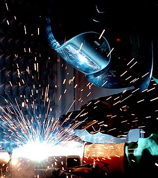
Arc welding is a welding process that is used to join metal to metal by using electricity to create enough heat to melt metal, and the melted metals, when cool, result in a binding of the metals. It is a type of welding that uses a welding power supply to create an electric arc between a metal stick ("electrode") and the base material to melt the metals at the point of contact. Arc welding power supplies can deliver either direct (DC) or alternating (AC) current to the work, while consumable or non-consumable electrodes are used.
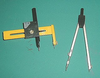
A compass, more accurately known as a pair of compasses, is a technical drawing instrument that can be used for inscribing circles or arcs. As dividers, it can also be used as a tool to mark out distances, in particular, on maps. Compasses can be used for mathematics, drafting, navigation and other purposes.

The steel square is a tool used in carpentry. Carpenters use various tools to lay out structures that are square, many of which are made of steel, but the name steel square refers to a specific long-armed square that has additional uses for measurement, especially of various angles. It consists of a long, wider arm and a shorter, narrower arm, which meet at an angle of 90 degrees. Today the steel square is more commonly referred to as the framing square or carpenter's square, and such squares are no longer invariably made of steel ; they can also be made of aluminum or polymers, which are light and resistant to rust.
Electric resistance welding (ERW) is a welding process where metal parts in contact are permanently joined by heating them with an electric current, melting the metal at the joint. Electric resistance welding is widely used, for example, in manufacture of steel pipe and in assembly of bodies for automobiles. The electric current can be supplied to electrodes that also apply clamping pressure, or may be induced by an external magnetic field. The electric resistance welding process can be further classified by the geometry of the weld and the method of applying pressure to the joint: spot welding, seam welding, flash welding, projection welding, for example. Some factors influencing heat or welding temperatures are the proportions of the workpieces, the metal coating or the lack of coating, the electrode materials, electrode geometry, electrode pressing force, electric current and length of welding time. Small pools of molten metal are formed at the point of most electrical resistance as an electric current is passed through the metal. In general, resistance welding methods are efficient and cause little pollution, but their applications are limited to relatively thin materials.

A special right triangle is a right triangle with some regular feature that makes calculations on the triangle easier, or for which simple formulas exist. For example, a right triangle may have angles that form simple relationships, such as 45°–45°–90°. This is called an "angle-based" right triangle. A "side-based" right triangle is one in which the lengths of the sides form ratios of whole numbers, such as 3 : 4 : 5, or of other special numbers such as the golden ratio. Knowing the relationships of the angles or ratios of sides of these special right triangles allows one to quickly calculate various lengths in geometric problems without resorting to more advanced methods.

An arrow is a graphical symbol, such as ← or →, or a pictogram, used to point or indicate direction. In its simplest form, an arrow is a triangle, chevron, or concave kite, usually affixed to a line segment or rectangle, and in more complex forms a representation of an actual arrow. The direction indicated by an arrow is the one along the length of the line or rectangle toward the single pointed end.

Butt welding is when two pieces of metal are placed end-to-end without overlap and then welded along the joint. Importantly, in a butt joint, the surfaces of the workpieces being joined are on the same plane and the weld metal remains within the planes of the surfaces.

Drafting tools may be used for measurement and layout of drawings, or to improve the consistency and speed of creation of standard drawing elements. Tools such as pens and pencils mark the drawing medium. Other tools such as straight edges, assist the operator in drawing straight lines, or assist the operator in drawing complicated shapes repeatedly. Various scales and the protractor are used to measure the lengths of lines and angles, allowing accurate scale drawing to be carried out. The compass is used to draw arcs and circles. A drawing board was used to hold the drawing media in place; later boards included drafting machines that sped the layout of straight lines and angles. Tools such as templates and lettering guides assisted in the drawing of repetitive elements such as circles, ellipses, schematic symbols and text. Other auxiliary tools were used for special drawing purposes or for functions related to the preparation and revision of drawings. The tools used for manual technical drawing have been displaced by the advent of computer-aided drawing, drafting and design (CADD).
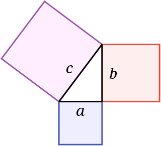
In mathematics, the Pythagorean theorem or Pythagoras' theorem is a fundamental relation in Euclidean geometry between the three sides of a right triangle. It states that the area of the square whose side is the hypotenuse is equal to the sum of the areas of the squares on the other two sides.

In metalworking, a welding joint is a point or edge where two or more pieces of metal or plastic are joined together. They are formed by welding two or more workpieces according to a particular geometry. There are five types of joints referred to by the American Welding Society: butt, corner, edge, lap, and tee. These types may have various configurations at the joint where actual welding can occur.

The symbols and conventions used in welding documentation are specified in national and international standards such as ISO 2553 Welded, brazed and soldered joints -- Symbolic representation on drawings and ISO 4063 Welding and allied processes -- Nomenclature of processes and reference numbers. The US standard symbols are outlined by the American National Standards Institute and the American Welding Society and are noted as "ANSI/AWS". Due in part to the growth of the oil industry, this symbol set was used during the 1990s in about 50% of the world's welding operations. An ISO committee sought to establish a global standard during this decade.
Weld purging is the act of removing, from the vicinity of the joint; oxygen, water vapour and any other gases or vapours that might oxidize or contaminate a welding joint as it is being welded and immediately after welding.


