
An electric motor is an electrical machine that converts electrical energy into mechanical energy. Most electric motors operate through the interaction between the motor's magnetic field and electric current in a wire winding to generate force in the form of torque applied on the motor's shaft. An electric generator is mechanically identical to an electric motor, but operates in reverse, converting mechanical energy into electrical energy.

An induction motor or asynchronous motor is an AC electric motor in which the electric current in the rotor that produces torque is obtained by electromagnetic induction from the magnetic field of the stator winding. An induction motor therefore needs no electrical connections to the rotor. An induction motor's rotor can be either wound type or squirrel-cage type.
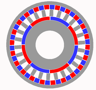
A rotating magnetic field is the resultant magnetic field produced by a system of coils symmetrically placed and supplied with polyphase currents. A rotating magnetic field can be produced by a poly-phase current or by a single phase current provided that, in the latter case, two field windings are supplied and are so designed that the two resulting magnetic fields generated thereby are out of phase.

A synchronous electric motor is an AC electric motor in which, at steady state, the rotation of the shaft is synchronized with the frequency of the supply current; the rotation period is exactly equal to an integer number of AC cycles. Synchronous motors use electromagnets as the stator of the motor which create a magnetic field that rotates in time with the oscillations of the current. The rotor with permanent magnets or electromagnets turns in step with the stator field at the same rate and as a result, provides the second synchronized rotating magnet field. A synchronous motor is termed doubly fed if it is supplied with independently excited multiphase AC electromagnets on both the rotor and stator.

A brushless DC electric motor (BLDC), also known as an electronically commutated motor, is a synchronous motor using a direct current (DC) electric power supply. It uses an electronic controller to switch DC currents to the motor windings producing magnetic fields that effectively rotate in space and which the permanent magnet rotor follows. The controller adjusts the phase and amplitude of the current pulses that control the speed and torque of the motor. It is an improvement on the mechanical commutator (brushes) used in many conventional electric motors.

A DC motor is an electrical motor that uses direct current (DC) to produce mechanical force. The most common types rely on magnetic forces produced by currents in the coils. Nearly all types of DC motors have some internal mechanism, either electromechanical or electronic, to periodically change the direction of current in part of the motor.
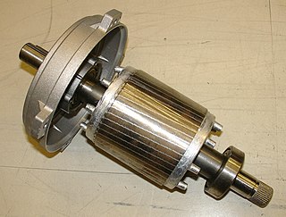
A squirrel-cage rotor is the rotating part of the common squirrel-cage induction motor. It consists of a cylinder of steel laminations, with aluminum or copper conductors embedded in its surface. In operation, the non-rotating stator winding is connected to an alternating current power source; the alternating current in the stator produces a rotating magnetic field. The rotor winding has current induced in it by the stator field, like a transformer except that the current in the rotor is varying at the stator field rotation rate minus the physical rotation rate. The interaction of the magnetic fields in the stator and the currents in the rotor produce a torque on the rotor.

The shaded-pole motor is the original type of AC single-phase motor, dating back to at least as early as 1890. A shaded-pole motor is a small motor with either two or four poles, in which the auxiliary winding is composed of a copper ring or bar surrounding a portion of each pole to produce a weakly rotating magnetic field. When single phase AC supply is applied to the stator winding, due to shading provided to the poles, a rotating magnetic field is generated. This auxiliary single-turn winding is called a shading coil. Currents induced in this coil by the magnetic field create a second electrical phase by delaying the phase of magnetic flux change for that pole enough to provide a 2-phase rotating magnetic field. The direction of rotation is from the unshaded side to the shaded (ring) side of the pole. Since the phase angle between the shaded and unshaded sections is small, shaded-pole motors produce only a small starting torque relative to torque at full speed. Shaded-pole motors of the asymmetrical type shown are only reversible by disassembly and flipping over the stator, though some similar looking motors have small, switch-shortable auxiliary windings of thin wire instead of thick copper bars and can reverse electrically. Another method of electrical reversing involves four coils.

The universal motor is a type of electric motor that can operate on either AC or DC power and uses an electromagnet as its stator to create its magnetic field. It is a commutated series-wound motor where the stator's field coils are connected in series with the rotor windings through a commutator. It is often referred to as an AC series motor. The universal motor is very similar to a DC series motor in construction, but is modified slightly to allow the motor to operate properly on AC power. This type of electric motor can operate well on AC because the current in both the field coils and the armature will alternate synchronously with the supply. Hence the resulting mechanical force will occur in a consistent direction of rotation, independent of the direction of applied voltage, but determined by the commutator and polarity of the field coils.
A field coil is an electromagnet used to generate a magnetic field in an electro-magnetic machine, typically a rotating electrical machine such as a motor or generator. It consists of a coil of wire through which a current flows.
Cogging torque of electrical motors is the torque due to the interaction between the permanent magnets of the rotor and the stator slots of a permanent magnet machine. It is also known as detent or no-current torque. This torque is position dependent and its periodicity per revolution depends on the number of magnetic poles and the number of teeth on the stator. Cogging torque is an undesirable component for the operation of such a motor. It is especially prominent at lower speeds, with the symptom of jerkiness. Cogging torque results in torque as well as speed ripple; however, at high speed the motor moment of inertia filters out the effect of cogging torque.

A reluctance motor is a type of electric motor that induces non-permanent magnetic poles on the ferromagnetic rotor. The rotor does not have any windings. It generates torque through magnetic reluctance.

An AC motor is an electric motor driven by an alternating current (AC). The AC motor commonly consists of two basic parts, an outside stator having coils supplied with alternating current to produce a rotating magnetic field, and an inside rotor attached to the output shaft producing a second rotating magnetic field. The rotor magnetic field may be produced by permanent magnets, reluctance saliency, or DC or AC electrical windings.

The rotor is a moving component of an electromagnetic system in the electric motor, electric generator, or alternator. Its rotation is due to the interaction between the windings and magnetic fields which produces a torque around the rotor's axis.
Electromagnetic brakes or EM brakes are used to slow or stop vehicles using electromagnetic force to apply mechanical resistance (friction). They were originally called electro-mechanical brakes but over the years the name changed to "electromagnetic brakes", referring to their actuation method which is generally unrelated to modern electro-mechanical brakes. Since becoming popular in the mid-20th century, especially in trains and trams, the variety of applications and brake designs has increased dramatically, but the basic operation remains the same.
In electrical engineering, electric machine is a general term for machines using electromagnetic forces, such as electric motors, electric generators, and others. They are electromechanical energy converters: an electric motor converts electricity to mechanical power while an electric generator converts mechanical power to electricity. The moving parts in a machine can be rotating or linear. While transformers are occasionally called "static electric machines", since they do not have moving parts, generally they are not considered "machines", but as electrical devices "closely related" to the electrical machines.

A wound-rotor motor, also known as slip ring-rotor motor, is a type of induction motor where the rotor windings are connected through slip rings to external resistance. Adjusting the resistance allows control of the speed/torque characteristic of the motor. Wound-rotor motors can be started with low inrush current, by inserting high resistance into the rotor circuit; as the motor accelerates, the resistance can be decreased.
A magnetic gear resembles the traditional mechanical gear in geometry and function, using magnets instead of teeth. As two opposing magnets approach each other, they repel; when placed on two rings the magnets will act like teeth. As opposed to conventional hard contact backlash in a spur gear, where a gear may rotate freely until in contact with the next gear, the magnetic gear has a springy backlash. As a result magnetic gears are able to apply pressure no matter the relative angle. Although they provide a motion ratio as a traditional gear, such gears work without touching and are immune to wear of mating surfaces, have no noise, and may slip without damage.
Electromagnetically induced acoustic noise, electromagnetically excited acoustic noise, or more commonly known as coil whine, is audible sound directly produced by materials vibrating under the excitation of electromagnetic forces. Some examples of this noise include the mains hum, hum of transformers, the whine of some rotating electric machines, or the buzz of fluorescent lamps. The hissing of high voltage transmission lines is due to corona discharge, not magnetism.

An axial flux motor is a geometry of electric motor construction where the gap between the rotor and stator, and therefore the direction of magnetic flux between the two, is aligned parallel with the axis of rotation, rather than radially as with the concentric cylindrical geometry of the more common radial flux motor. With axial flux geometry torque increases with the cube of the rotor diameter, whereas in a radial flux the increase is only quadratic. Axial flux motors have a larger magnetic surface and overall surface area than radial flux motors for a given volume.
