
In electromagnetism, there are two kinds of dipoles:
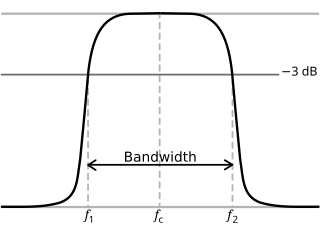
In physics and electrical engineering, a cutoff frequency, corner frequency, or break frequency is a boundary in a system's frequency response at which energy flowing through the system begins to be reduced rather than passing through.
The propagation constant of a sinusoidal electromagnetic wave is a measure of the change undergone by the amplitude and phase of the wave as it propagates in a given direction. The quantity being measured can be the voltage, the current in a circuit, or a field vector such as electric field strength or flux density. The propagation constant itself measures the change per unit length, but it is otherwise dimensionless. In the context of two-port networks and their cascades, propagation constant measures the change undergone by the source quantity as it propagates from one port to the next.
The wave impedance of an electromagnetic wave is the ratio of the transverse components of the electric and magnetic fields. For a transverse-electric-magnetic (TEM) plane wave traveling through a homogeneous medium, the wave impedance is everywhere equal to the intrinsic impedance of the medium. In particular, for a plane wave travelling through empty space, the wave impedance is equal to the impedance of free space. The symbol Z is used to represent it and it is expressed in units of ohms. The symbol η (eta) may be used instead of Z for wave impedance to avoid confusion with electrical impedance.

In electrical engineering, electrical impedance is the measure of the opposition that a circuit presents to a current when a voltage is applied.

Coaxial cable, or coax is a type of electrical cable consisting of an inner conductor surrounded by a concentric conducting shield, with the two separated by a dielectric ; many coaxial cables also have a protective outer sheath or jacket. The term coaxial refers to the inner conductor and the outer shield sharing a geometric axis.
In electromagnetics, an antenna's power gain or simply gain is a key performance number which combines the antenna's directivity and electrical efficiency. In a transmitting antenna, the gain describes how well the antenna converts input power into radio waves headed in a specified direction. In a receiving antenna, the gain describes how well the antenna converts radio waves arriving from a specified direction into electrical power. When no direction is specified, gain is understood to refer to the peak value of the gain, the gain in the direction of the antenna's main lobe. A plot of the gain as a function of direction is called the gain pattern or radiation pattern.

Twin-lead cable is a two-conductor flat cable used as a balanced transmission line to carry radio frequency (RF) signals. It is constructed of two stranded or solid copper or copper-clad steel wires, held a precise distance apart by a plastic ribbon. The uniform spacing of the wires is the key to the cable's function as a transmission line; any abrupt changes in spacing would reflect some of the signal back toward the source. The plastic also covers and insulates the wires. It is available with several different values of characteristic impedance, the most common type is 300 ohm.

In radio and telecommunications a dipole antenna or doublet is the simplest and most widely used class of antenna. The dipole is any one of a class of antennas producing a radiation pattern approximating that of an elementary electric dipole with a radiating structure supporting a line current so energized that the current has only one node at each end. A dipole antenna commonly consists of two identical conductive elements such as metal wires or rods. The driving current from the transmitter is applied, or for receiving antennas the output signal to the receiver is taken, between the two halves of the antenna. Each side of the feedline to the transmitter or receiver is connected to one of the conductors. This contrasts with a monopole antenna, which consists of a single rod or conductor with one side of the feedline connected to it, and the other side connected to some type of ground. A common example of a dipole is the "rabbit ears" television antenna found on broadcast television sets.

An LC circuit, also called a resonant circuit, tank circuit, or tuned circuit, is an electric circuit consisting of an inductor, represented by the letter L, and a capacitor, represented by the letter C, connected together. The circuit can act as an electrical resonator, an electrical analogue of a tuning fork, storing energy oscillating at the circuit's resonant frequency.
In telecommunications, particularly in radio frequency, signal strength refers to the transmitter power output as received by a reference antenna at a distance from the transmitting antenna. High-powered transmissions, such as those used in broadcasting, are expressed in dB-millivolts per metre (dBmV/m). For very low-power systems, such as mobile phones, signal strength is usually expressed in dB-microvolts per metre (dBμV/m) or in decibels above a reference level of one milliwatt (dBm). In broadcasting terminology, 1 mV/m is 1000 μV/m or 60 dBμ.

The rectangular function is defined as
An isotropic radiator is a theoretical point source of electromagnetic or sound waves which radiates the same intensity of radiation in all directions. It has no preferred direction of radiation. It radiates uniformly in all directions over a sphere centred on the source. Isotropic radiators are used as reference radiators with which other sources are compared, for example in determining the gain of antennas. A coherent isotropic radiator of electromagnetic waves is theoretically impossible, but incoherent radiators can be built. An isotropic sound radiator is possible because sound is a longitudinal wave.

An electromagnetic reverberation chamber is an environment for electromagnetic compatibility (EMC) testing and other electromagnetic investigations. Electromagnetic reverberation chambers have been introduced first by H.A. Mendes in 1968. A reverberation chamber is screened room with a minimum of absorption of electromagnetic energy. Due to the low absorption very high field strength can be achieved with moderate input power. A reverberation chamber is a cavity resonator with a high Q factor. Thus, the spatial distribution of the electrical and magnetic field strengths is strongly inhomogeneous. To reduce this inhomogeneity, one or more tuners (stirrers) are used. A tuner is a construction with large metallic reflectors that can be moved to different orientations in order to achieve different boundary conditions. The Lowest Usable Frequency (LUF) of a reverberation chamber depends on the size of the chamber and the design of the tuner. Small chambers have a higher LUF than large chambers.

Electrical resonance occurs in an electric circuit at a particular resonant frequency when the impedances or admittances of circuit elements cancel each other. In some circuits, this happens when the impedance between the input and output of the circuit is almost zero and the transfer function is close to one.
Antenna measurement techniques refers to the testing of antennas to ensure that the antenna meets specifications or simply to characterize it. Typical parameters of antennas are gain, bandwidth, radiation pattern, beamwidth, polarization, and impedance.

Plasma parameters define various characteristics of a plasma, an electrically conductive collection of charged particles that responds collectively to electromagnetic forces. Plasma typically takes the form of neutral gas-like clouds or charged ion beams, but may also include dust and grains. The behaviour of such particle systems can be studied statistically.
The Frank–Tamm formula yields the amount of Cherenkov radiation emitted on a given frequency as a charged particle moves through a medium at superluminal velocity. It is named for Russian physicists Ilya Frank and Igor Tamm who developed the theory of the Cherenkov effect in 1937, for which they were awarded a Nobel Prize in Physics in 1958.
An LC circuit can be quantized using the same methods as for the quantum harmonic oscillator. An LC circuit is a variety of resonant circuit, and consists of an inductor, represented by the letter L, and a capacitor, represented by the letter C. When connected together, an electric current can alternate between them at the circuit's resonant frequency:
Dipole field strength in free space, in telecommunications, is the electric field strength caused by a half wave dipole under ideal conditions. The actual field strength in terrestrial environments is calculated by empirical formulas based on this field strength.


