
In antenna theory, a phased array usually means an electronically scanned array, a computer-controlled array of antennas which creates a beam of radio waves that can be electronically steered to point in different directions without moving the antennas. The general theory of an electromagnetic phased array also finds applications in ultrasonic and medical imaging application and in optics optical phased array.

In telecommunications and radar, a reflective array antenna is a class of directive antennas in which multiple driven elements are mounted in front of a flat surface designed to reflect the radio waves in a desired direction. They are a type of array antenna. They are often used in the VHF and UHF frequency bands. VHF examples are generally large and resemble a highway billboard, so they are sometimes called billboard antennas. Other names are bedspring array and bowtie array depending on the type of elements making up the antenna. The curtain array is a larger version used by shortwave radio broadcasting stations.

In radio engineering, an antenna or aerial is an electronic device that converts an alternating electric current into radio waves, or radio waves into an electric current. It is the interface between radio waves propagating through space and electric currents moving in metal conductors, used with a transmitter or receiver. In transmission, a radio transmitter supplies an electric current to the antenna's terminals, and the antenna radiates the energy from the current as electromagnetic waves. In reception, an antenna intercepts some of the power of a radio wave in order to produce an electric current at its terminals, that is applied to a receiver to be amplified. Antennas are essential components of all radio equipment.

Beam tilt is used in radio to aim the main lobe of the vertical plane radiation pattern of an antenna below the horizontal plane.

Very High Frequency Omnidirectional Range Station (VOR) is a type of short-range radio navigation system for aircraft, enabling aircraft with a receiving unit to determine its position and stay on course by receiving radio signals transmitted by a network of fixed ground radio beacons. It uses frequencies in the very high frequency (VHF) band from 108.00 to 117.95 MHz. Developed in the United States beginning in 1937 and deployed by 1946, VOR became the standard air navigational system in the world, used by both commercial and general aviation, until supplanted by satellite navigation systems such as GPS in the early 21st century. As such, VOR stations are being gradually decommissioned. In 2000 there were about 3,000 VOR stations operating around the world, including 1,033 in the US, but by 2013 the number in the US had been reduced to 967. The United States is decommissioning approximately half of its VOR stations and other legacy navigation aids as part of a move to performance-based navigation, while still retaining a "Minimum Operational Network" of VOR stations as a backup to GPS. In 2015, the UK planned to reduce the number of stations from 44 to 19 by 2020.

Direction finding (DF), or radio direction finding (RDF), is the use of radio waves to determine the direction to a radio source. The source may be a cooperating radio transmitter or may be an inadvertant source, a naturally-occurring radio source, or an illicit or enemy system. Radio direction finding differs from radar in that only the direction is determined by any one receiver; a radar system usually also gives a distance to the object of interest, as well as direction. By triangulation, the location of a radio source can be determined by measuring its direction from two or more locations. Radio direction finding is used in radio navigation for ships and aircraft, to locate emergency transmitters for search and rescue, for tracking wildlife, and to locate illegal or interfering transmitters. During the Second World War, radio direction finding was used by both sides to locate and direct aircraft, surface ships, and submarines.

An active electronically scanned array (AESA) is a type of phased array antenna, which is a computer-controlled antenna array in which the beam of radio waves can be electronically steered to point in different directions without moving the antenna. In the AESA, each antenna element is connected to a small solid-state transmit/receive module (TRM) under the control of a computer, which performs the functions of a transmitter and/or receiver for the antenna. This contrasts with a passive electronically scanned array (PESA), in which all the antenna elements are connected to a single transmitter and/or receiver through phase shifters under the control of the computer. AESA's main use is in radar, and these are known as active phased array radar (APAR).

The Beverage antenna or "wave antenna" is a long-wire receiving antenna mainly used in the low frequency and medium frequency radio bands, invented by Harold H. Beverage in 1921. It is used by amateur radio operators, shortwave listeners, longwave radio DXers and for military applications.

Beamforming or spatial filtering is a signal processing technique used in sensor arrays for directional signal transmission or reception. This is achieved by combining elements in an antenna array in such a way that signals at particular angles experience constructive interference while others experience destructive interference. Beamforming can be used at both the transmitting and receiving ends in order to achieve spatial selectivity. The improvement compared with omnidirectional reception/transmission is known as the directivity of the array.

In antenna engineering, sidelobes are the lobes of the far field radiation pattern of an antenna or other radiation source, that are not the main lobe.
Smart antennas are antenna arrays with smart signal processing algorithms used to identify spatial signal signatures such as the direction of arrival (DOA) of the signal, and use them to calculate beamforming vectors which are used to track and locate the antenna beam on the mobile/target. Smart antennas should not be confused with reconfigurable antennas, which have similar capabilities but are single element antennas and not antenna arrays.

A loop antenna is a radio antenna consisting of a loop or coil of wire, tubing, or other electrical conductor, that for transmitting is usually fed by a balanced power source or for receiving feeds a balanced load. Within this physical description there are two distinct types:
In radio electronics, a null is a direction in an antenna's radiation pattern where the antenna radiates almost no radio waves, so the far field signal strength is a local minimum. Nulls occur because different parts of an antenna radiate radio waves of different phase. In directions at which the antenna radiates equal amplitude radio waves of opposite phase, the radio waves cancel, resulting in little or no radio power being radiated in that direction. In other directions the radio waves from different parts of the antenna are in phase and reinforce, resulting in a maximum signal strength in the radiation pattern, called a lobe.

Sodar, an acronym of sonic detection and ranging, is a meteorological instrument used as a wind profiler based on the scattering of sound waves by atmospheric turbulence. Sodar equipment is used to measure wind speed at various heights above the ground, and the thermodynamic structure of the lower layer of the atmosphere.

A passive electronically scanned array (PESA), also known as passive phased array, is an antenna in which the beam of radio waves can be electronically steered to point in different directions, in which all the antenna elements are connected to a single transmitter and/or receiver. The largest use of phased arrays is in radars. Most phased array radars in the world are PESA. The civilian microwave landing system uses PESA transmit-only arrays.

Advanced Extremely High Frequency (AEHF) is a constellation of communications satellites operated by the United States Space Force. They are used to relay secure communications for the United States Armed Forces, the British Armed Forces, the Canadian Armed Forces, the Netherlands Armed Forces and the Australian Defence Force. The system consists of six satellites in geostationary orbits. The final satellite was launched on 26 March 2020. AEHF is backward compatible with, and replaces, the older Milstar system and will operate at 44 GHz uplink and 20 GHz downlink. The AEHF system is a joint service communications system that provides survivable, global, secure, protected, and jam-resistant communications for high-priority military ground, sea and air assets.
An antenna array is a set of multiple connected antennas which work together as a single antenna, to transmit or receive radio waves. The individual antennas are usually connected to a single receiver or transmitter by feedlines that feed the power to the elements in a specific phase relationship. The radio waves radiated by each individual antenna combine and superpose, adding together to enhance the power radiated in desired directions, and cancelling to reduce the power radiated in other directions. Similarly, when used for receiving, the separate radio frequency currents from the individual antennas combine in the receiver with the correct phase relationship to enhance signals received from the desired directions and cancel signals from undesired directions. More sophisticated array antennas may have multiple transmitter or receiver modules, each connected to a separate antenna element or group of elements.
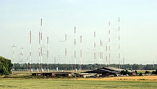
Curtain arrays are a class of large multielement directional radio transmitting wire antennas, used in the short-wave radio bands. They constitute a type of reflective array antenna, consisting of multiple wire dipole antennas, suspended in a vertical plane, often positioned in front of a "curtain" reflector made of a flat vertical screen of many long parallel wires. These are suspended by support wires strung between pairs of tall steel towers, reaching heights of up to 90 m high. Primarily employed for long-distance skywave transmission, they emit a beam of radio waves at a shallow angle into the sky just above the horizon, which is then reflected by the ionosphere back to Earth beyond the horizon. Curtain arrays are extensively used by international short-wave radio stations for broadcasting to large areas at transcontinental distances.
In radio systems, many different antenna types are used whose properties are especially crafted for particular applications.
A Butler matrix is a beamforming network used to feed a phased array of antenna elements. Its purpose is to control the direction of a beam, or beams, of radio transmission. It consists of an matrix with hybrid couplers and fixed-value phase shifters at the junctions. The device has input ports to which power is applied, and output ports to which antenna elements are connected. The Butler matrix feeds power to the elements with a progressive phase difference between elements such that the beam of radio transmission is in the desired direction. The beam direction is controlled by switching power to the desired beam port. More than one beam, or even all of them can be activated simultaneously.