Superheterodyne transmitter is a radio or TV transmitter which uses an intermediate frequency signal in addition to radio frequency signal.
Superheterodyne transmitter is a radio or TV transmitter which uses an intermediate frequency signal in addition to radio frequency signal.

There are two types of transmitters. In some transmitters, the information signal (audio (AF), video (VF) etc.) modulates the radio frequency (RF) signal. These direct modulation transmitters are relatively simple transmitters.
In more complicated transmitters which are called superheterodyne, the information signal modulates an intermediate frequency (IF) signal. After stages for correction, equalization and sometimes amplification, the IF signal is converted to an RF signal by a stage named frequency mixer or frequency converter. Superheterodyne transmitters are more complex than direct modulation transmitters.[ citation needed ]
Let
In direct modulation transmitter the information signal modulates the RF carrier. If the type of modulation is conventional amplitude modulation the RF output is,
Likewise in superheterodyne transmitter the modulated IF is;
This signal is applied to a frequency mixer. The other input to the mixer is a high frequency subcarrier signal.
The two signals are multiplied to give;
Applying well known rules of trigonometry;
A filter at the output of the mixer filters out one of the terms at the right (usually the summation) leaving RF
Here is the required angular RF; i.e.,
After phase and amplitude equalization,

Amplitude modulation (AM) is a modulation technique used in electronic communication, most commonly for transmitting messages with a radio wave. In amplitude modulation, the amplitude of the wave is varied in proportion to that of the message signal, such as an audio signal. This technique contrasts with angle modulation, in which either the frequency of the carrier wave is varied, as in frequency modulation, or its phase, as in phase modulation.
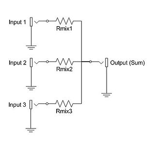
An electronic mixer is a device that combines two or more electrical or electronic signals into one or two composite output signals. There are two basic circuits that both use the term mixer, but they are very different types of circuits: additive mixers and multiplicative mixers. Additive mixers are also known as analog adders to distinguish from the related digital adder circuits.
Phase modulation (PM) is a modulation pattern for conditioning communication signals for transmission. It encodes a message signal as variations in the instantaneous phase of a carrier wave. Phase modulation is one of the two principal forms of angle modulation, together with frequency modulation.
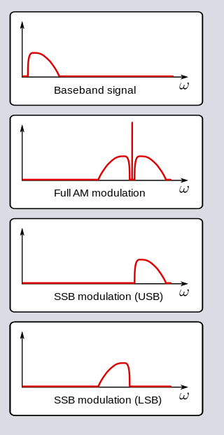
In radio communications, single-sideband modulation (SSB) or single-sideband suppressed-carrier modulation (SSB-SC) is a type of modulation used to transmit information, such as an audio signal, by radio waves. A refinement of amplitude modulation, it uses transmitter power and bandwidth more efficiently. Amplitude modulation produces an output signal the bandwidth of which is twice the maximum frequency of the original baseband signal. Single-sideband modulation avoids this bandwidth increase, and the power wasted on a carrier, at the cost of increased device complexity and more difficult tuning at the receiver.

A superheterodyne receiver, often shortened to superhet, is a type of radio receiver that uses frequency mixing to convert a received signal to a fixed intermediate frequency (IF) which can be more conveniently processed than the original carrier frequency. It was long believed to have been invented by US engineer Edwin Armstrong, but after some controversy the earliest patent for the invention is now credited to French radio engineer and radio manufacturer Lucien Lévy. Virtually all modern radio receivers use the superheterodyne principle.

In telecommunications and signal processing, baseband is the range of frequencies occupied by a signal that has not been modulated to higher frequencies. Baseband signals typically originate from transducers, converting some other variable into an electrical signal. For example, the electronic output of a microphone is a baseband signal that is analogous to the applied voice audio. In conventional analog radio broadcasting, the baseband audio signal is used to modulate an RF carrier signal of a much higher frequency.
Double-sideband suppressed-carrier transmission (DSB-SC) is transmission in which frequencies produced by amplitude modulation (AM) are symmetrically spaced above and below the carrier frequency and the carrier level is reduced to the lowest practical level, ideally being completely suppressed.

A heterodyne is a signal frequency that is created by combining or mixing two other frequencies using a signal processing technique called heterodyning, which was invented by Canadian inventor-engineer Reginald Fessenden. Heterodyning is used to shift signals from one frequency range into another, and is also involved in the processes of modulation and demodulation. The two input frequencies are combined in a nonlinear signal-processing device such as a vacuum tube, transistor, or diode, usually called a mixer.

A phase-locked loop or phase lock loop (PLL) is a control system that generates an output signal whose phase is related to the phase of an input signal. There are several different types; the simplest is an electronic circuit consisting of a variable frequency oscillator and a phase detector in a feedback loop. The oscillator's frequency and phase are controlled proportionally by an applied voltage, hence the term voltage-controlled oscillator (VCO). The oscillator generates a periodic signal of a specific frequency, and the phase detector compares the phase of that signal with the phase of the input periodic signal, to adjust the oscillator to keep the phases matched.
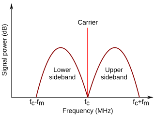
In radio communications, a sideband is a band of frequencies higher than or lower than the carrier frequency, that are the result of the modulation process. The sidebands carry the information transmitted by the radio signal. The sidebands comprise all the spectral components of the modulated signal except the carrier. The signal components above the carrier frequency constitute the upper sideband (USB), and those below the carrier frequency constitute the lower sideband (LSB). All forms of modulation produce sidebands.
A product detector is a type of demodulator used for AM and SSB signals. Rather than converting the envelope of the signal into the decoded waveform like an envelope detector, the product detector takes the product of the modulated signal and a local oscillator, hence the name. A product detector is a frequency mixer.
In electronics, a mixer, or frequency mixer, is an electrical circuit that creates new frequencies from two signals applied to it. In its most common application, two signals are applied to a mixer, and it produces new signals at the sum and difference of the original frequencies. Other frequency components may also be produced in a practical frequency mixer.

An LC circuit, also called a resonant circuit, tank circuit, or tuned circuit, is an electric circuit consisting of an inductor, represented by the letter L, and a capacitor, represented by the letter C, connected together. The circuit can act as an electrical resonator, an electrical analogue of a tuning fork, storing energy oscillating at the circuit's resonant frequency.
In mathematics and signal processing, an analytic signal is a complex-valued function that has no negative frequency components. The real and imaginary parts of an analytic signal are real-valued functions related to each other by the Hilbert transform.

In physics and engineering, a phasor is a complex number representing a sinusoidal function whose amplitude, angular frequency, and initial phase are time-invariant. It is related to a more general concept called analytic representation, which decomposes a sinusoid into the product of a complex constant and a factor depending on time and frequency. The complex constant, which depends on amplitude and phase, is known as a phasor, or complex amplitude, and sinor or even complexor.
A resistor–inductor circuit, or RL filter or RL network, is an electric circuit composed of resistors and inductors driven by a voltage or current source. A first-order RL circuit is composed of one resistor and one inductor, either in series driven by a voltage source or in parallel driven by a current source. It is one of the simplest analogue infinite impulse response electronic filters.

A carrier recovery system is a circuit used to estimate and compensate for frequency and phase differences between a received signal's carrier wave and the receiver's local oscillator for the purpose of coherent demodulation.
In electronics, complex gain is the effect that circuitry has on the amplitude and phase of a sine wave signal. The term complex is used because mathematically this effect can be expressed as a complex number.
Differential gain is a kind of linearity distortion that affects the amplification and transmission of analog signals. It can visibly affect color saturation in analog TV broadcasting.
Differential phase is a kind of linearity distortion which affects the color hue in TV broadcasting.


