Ways electronic components fail and prevention measures
Failed IC in a laptop. Wrong input polarity has caused massive overheating of the chip and burned the plastic casing.
Electronic components have a wide range of failure modes. These can be classified in various ways, such as by time or cause. Failures can be caused by excess temperature, excess current or voltage, ionizing radiation, mechanical shock, stress or impact, and many other causes. In semiconductor devices, problems in the device package may cause failures due to contamination, mechanical stress of the device, or open or short circuits.
Failures most commonly occur near the beginning and near the ending of the lifetime of the parts, resulting in the bathtub curve graph of failure rates. Burn-in procedures are used to detect early failures. In semiconductor devices, parasitic structures, irrelevant for normal operation, become important in the context of failures; they can be both a source and protection against failure.
Applications such as aerospace systems, life support systems, telecommunications, railway signals, and computers use great numbers of individual electronic components. Analysis of the statistical properties of failures can give guidance in designs to establish a given level of reliability. For example, power-handling ability of a resistor may be greatly derated when applied in high-altitude aircraft to obtain adequate service life. A sudden fail-open fault can cause multiple secondary failures if it is fast and the circuit contains an inductance; this causes large voltage spikes, which may exceed 500 volts. A broken metallisation on a chip may thus cause secondary overvoltage damage.[1]Thermal runaway can cause sudden failures including melting, fire or explosions.
Packaging failures
The majority of electronic parts failures are packaging-related.[citation needed] Packaging, as the barrier between electronic parts and the environment, is very susceptible to environmental factors. Thermal expansion produces mechanical stresses that may cause material fatigue, especially when the thermal expansion coefficients of the materials are different. Humidity and aggressive chemicals can cause corrosion of the packaging materials and leads, potentially breaking them and damaging the inside parts, leading to electrical failure. Exceeding the allowed environmental temperature range can cause overstressing of wire bonds, thus tearing the connections loose, cracking the semiconductor dies, or causing packaging cracks. Humidity and subsequent high temperature heating may also cause cracking, as may mechanical damage or shock.
During encapsulation, bonding wires can be severed, shorted, or touch the chip die, usually at the edge. Dies can crack due to mechanical overstress or thermal shock; defects introduced during processing, like scribing, can develop into fractures. Lead frames may contain excessive material or burrs, causing shorts. Ionic contaminants like alkali metals and halogens can migrate from the packaging materials to the semiconductor dies, causing corrosion or parameter deterioration. Glass-metal seals commonly fail by forming radial cracks that originate at the pin-glass interface and permeate outwards; other causes include a weak oxide layer on the interface and poor formation of a glass meniscus around the pin.[2]
Various gases may be present in the package cavity, either as impurities trapped during manufacturing, outgassing of the materials used, or chemical reactions, as is when the packaging material gets overheated (the products are often ionic and facilitate corrosion with delayed failure). To detect this, helium is often in the inert atmosphere inside the packaging as a tracer gas to detect leaks during testing. Carbon dioxide and hydrogen may form from organic materials, moisture is outgassed by polymers and amine-cured epoxies outgas ammonia. Formation of cracks and intermetallic growth in die attachments may lead to formation of voids and delamination, impairing heat transfer from the chip die to the substrate and heatsink and causing a thermal failure. As some semiconductors like silicon and gallium arsenide are infrared-transparent, infrared microscopy can check the integrity of die bonding and under-die structures.[2]
Red phosphorus, used as a charring-promoter flame retardant, facilitates silver migration when present in packaging. It is normally coated with aluminium hydroxide; if the coating is incomplete, the phosphorus particles oxidize to the highly hygroscopicphosphorus pentoxide, which reacts with moisture to phosphoric acid. This is a corrosive electrolyte that in the presence of electric fields facilitates dissolution and migration of silver, short-circuiting adjacent packaging pins, lead frame leads, tie bars, chip mount structures, and chip pads. The silver bridge may be interrupted by thermal expansion of the package; thus, disappearance of the shorting when the chip is heated and its reappearance after cooling is an indication of this problem.[3] Delamination and thermal expansion may move the chip die relative to the packaging, deforming and possibly shorting or cracking the bonding wires.[1]
Contact failures
Electrical contacts exhibit ubiquitous contact resistance, the magnitude of which is governed by surface structure and the composition of surface layers.[4] Ideally contact resistance should be low and stable, however weak contact pressure, mechanical vibration, corrosion, and the formation of passivizing oxide layers and contacts can alter contact resistance significantly, leading to resistance heating and circuit failure.
Soldered joints can fail in many ways like electromigration and formation of brittle intermetallic layers. Some failures show only at extreme joint temperatures, hindering troubleshooting. Thermal expansion mismatch between the printed circuit board material and its packaging strains the part-to-board bonds; while leaded parts can absorb the strain by bending, leadless parts rely on the solder to absorb stresses. Thermal cycling may lead to fatigue cracking of the solder joints, especially with elastic solders; various approaches are used to mitigate such incidents. Loose particles, like bonding wire and weld flash, can form in the device cavity and migrate inside the packaging, causing often intermittent and shock-sensitive shorts. Corrosion may cause buildup of oxides and other nonconductive products on the contact surfaces. When closed, these then show unacceptably high resistance; they may also migrate and cause shorts.[2]Tin whiskers can form on tin-coated metals like the internal side of the packagings; loose whiskers then can cause intermittent short circuits inside the packaging. Cables, in addition to the methods described above, may fail by fraying and fire damage.
Printed circuit board failures
Severe PCB corrosion from a leaky PCB mounted Ni-Cd battery
Printed circuit boards (PCBs) are vulnerable to environmental influences; for example, the traces are corrosion-prone and may be improperly etched leaving partial shorts, while the vias may be insufficiently plated through or filled with solder. The traces may crack under mechanical loads, often resulting in unreliable PCB operation. Residues of solder flux may facilitate corrosion; those of other materials on PCBs can cause electrical leaks. Polar covalent compounds can attract moisture like antistatic agents, forming a thin layer of conductive moisture between the traces; ionic compounds like chlorides tend to facilitate corrosion. Alkali metal ions may migrate through plastic packaging and influence the functioning of semiconductors. Chlorinated hydrocarbon residues may hydrolyze and release corrosive chlorides; these are problems that occur after years. Polar molecules may dissipate high-frequency energy, causing parasitic dielectric losses.
Above the glass transition temperature of PCBs, the resin matrix softens and becomes susceptible contaminant diffusion. For example, polyglycols from the solder flux can enter the board and increase its humidity intake, with corresponding deterioration of dielectric and corrosion properties.[5] Multi-layer substrates using ceramics suffer from many of the same problems.
Conductive anodic filaments (CAFs) may grow within the boards along the fibers of the composite material. Metal is introduced to a vulnerable surface typically from plating the vias, then migrates in presence of ions, moisture, and electrical potential; drilling damage and poor glass-resin bonding promotes such failures.[6] The formation of CAFs usually begins by poor glass-resin bonding; a layer of adsorbed moisture then provides a channel through which ions and corrosion products migrate. In presence of chloride ions, the precipitated material is atacamite; its semiconductive properties lead to increased current leakage, deteriorated dielectric strength, and short circuits between traces. Absorbed glycols from flux residues aggravate the problem. The difference in thermal expansion of the fibers and the matrix weakens the bond when the board is soldered; the lead-free solders which require higher soldering temperatures increase the occurrence of CAFs. Besides this, CAFs depend on absorbed humidity; below a certain threshold, they do not occur.[5] Delamination may occur to separate the board layers, cracking the vias and conductors to introduce pathways for corrosive contaminants and migration of conductive species.[6]
Relay failures
Every time the contacts of an electromechanical relay or contactor are opened or closed, there is a certain amount of contact wear. An electric arc occurs between the contact points (electrodes) both during the transition from closed to open (break) or from open to closed (make). The arc caused during the contact break (break arc) is akin to arc welding, as the break arc is typically more energetic and more destructive.[7]
The heat and current of the electrical arc across the contacts creates specific cone & crater formations from metal migration. In addition to the physical contact damage, there appears also a coating of carbon and other matter. This degradation drastically limits the overall operating life of a relay or contactor to a range of perhaps 100,000 operations, a level representing 1% or less than the mechanical life expectancy of the same device.[8]
Many failures result in generation of hot electrons. These are observable under an optical microscope, as they generate near-infrared photons detectable by a CCD camera. Latchups can be observed this way.[9] If visible, the location of failure may present clues to the nature of the overstress. Liquid crystal coatings can be used for localization of faults: cholesteric liquid crystals are thermochromic and are used for visualisation of locations of heat production on the chips, while nematic liquid crystals respond to voltage and are used for visualising current leaks through oxide defects and of charge states on the chip surface (particularly logical states).[2] Laser marking of plastic-encapsulated packages may damage the chip if glass spheres in the packaging line up and direct the laser to the chip.[3]
Examples of semiconductor failures relating to semiconductor crystals include:
Migration of charge carriers from floating gates. This limits the lifetime of stored data in EEPROM and flash EPROM structures.
Improper passivation. Corrosion is a significant source of delayed failures; semiconductors, metallic interconnects, and passivation glasses are all susceptible. The surface of semiconductors subjected to moisture has an oxide layer; the liberated hydrogen reacts with deeper layers of the material, yielding volatile hydrides.[10]
Parameter failures
Vias are a common source of unwanted serial resistance on chips; defective vias show unacceptably high resistance and therefore increase propagation delays. As their resistivity drops with increasing temperature, degradation of the maximum operating frequency of the chip the other way is an indicator of such a fault. Mousebites are regions where metallization has a decreased width; such defects usually do not show during electrical testing but present a major reliability risk. Increased current density in the mousebite can aggravate electromigration problems; a large degree of voiding is needed to create a temperature-sensitive propagation delay.[9]
Sometimes, circuit tolerances can make erratic behaviour difficult to trace; for example, a weak driver transistor, a higher series resistance and the capacitance of the gate of the subsequent transistor may be within tolerance but can significantly increase signal propagation delay. These can manifest only at specific environmental conditions, high clock speeds, low power supply voltages, and sometimes specific circuit signal states; significant variations can occur on a single die.[9] Overstress-induced damage like ohmic shunts or a reduced transistor output current can increase such delays, leading to erratic behavior. As propagation delays depend heavily on supply voltage, tolerance-bound fluctuations of the latter can trigger such behavior.
Degradation of IDSS[12] by gate sinking and hydrogen poisoning. This failure is the most common and easiest to detect, and is affected by reduction of the active channel of the transistor in gate sinking and depletion of the donor density in the active channel for hydrogen poisoning.
Degradation in gate leakage current. This occurs at accelerated life tests or high temperatures and is suspected to be caused by surface-state effects.
Degradation in pinch-off voltage. This is a common failure mode for gallium arsenide devices operating at high temperature, and primarily stems from semiconductor-metal interactions and degradation of gate metal structures, with hydrogen being another reason. It can be hindered by a suitable barrier metal between the contacts and gallium arsenide.
Increase in drain-to-source resistance. It is observed in high-temperature devices, and is caused by metal-semiconductor interactions, gate sinking and ohmic contact degradation.
Metallisation failures
Micro-photograph of a failed TO3 power transistor due to short circuit
Metallisation failures are more common and serious causes of FET transistor degradation than material processes; amorphous materials have no grain boundaries, hindering interdiffusion and corrosion.[13] Examples of such failures include:
Electromigration moving atoms out of active regions, causing dislocations and point defects acting as nonradiative recombination centers producing heat. This may occur with aluminium gates in MESFETs with RF signals, causing erratic drain current; electromigration in this case is called gate sinking. This issue does not occur with gold gates.[13] With structures having aluminium over a refractory metal barrier, electromigration primarily affects aluminium but not the refractory metal, causing the structure's resistance to erratically increase. Displaced aluminium may cause shorts to neighbouring structures; 0.5-4% of copper in the aluminium increases electromigration resistance, the copper accumulating on the alloy grain boundaries and increasing the energy needed to dislodge atoms from them.[14] Other than that, indium tin oxide and silver are subject to electromigration, causing leakage current and (in LEDs) nonradiative recombination along chip edges. In all cases, electromigration can cause changes in dimensions and parameters of the transistor gates and semiconductor junctions.
Mechanical stresses, high currents, and corrosive environments forming of whiskers and short circuits. These effects can occur both within packaging and on circuit boards.
Formation of silicon nodules. Aluminium interconnects may be silicon-doped to saturation during deposition to prevent alloy spikes. During thermal cycling, the silicon atoms may migrate and clump together forming nodules that act as voids, increasing local resistance and lowering device lifetime.[2]
Ohmic contact degradation between metallisation and semiconductor layers. With gallium arsenide, a layer of gold-germanium alloy (sometimes with nickel) is used to achieve low contact resistance; an ohmic contact is formed by diffusion of germanium, forming a thin, highly n-doped region under the metal facilitating the connection, leaving gold deposited over it. Gallium atoms may migrate through this layer and get scavenged by the gold above, creating a defect-rich gallium-depleted zone under the contact; gold and oxygen then migrate oppositely, resulting in increased resistance of the ohmic contact and depletion of effective doping level.[13] Formation of intermetallic compounds also plays a role in this failure mode.
Electrical overstress
Most stress-related semiconductor failures are electrothermal in nature microscopically; locally increased temperatures can lead to immediate failure by melting or vaporising metallisation layers, melting the semiconductor or by changing structures. Diffusion and electromigration tend to be accelerated by high temperatures, shortening the lifetime of the device; damage to junctions not leading to immediate failure may manifest as altered current–voltage characteristics of the junctions. Electrical overstress failures can be classified as thermally-induced, electromigration-related and electric field-related failures; examples of such failures include:
Thermal runaway, where clusters in the substrate cause localised loss of thermal conductivity, leading to damage producing more heat; the most common causes are voids caused by incomplete soldering, electromigration effects and Kirkendall voiding. Clustered distribution of current density over the junction or current filaments lead to current crowding localised hot spots, which may evolve to a thermal runaway.
Reverse bias. Some semiconductor devices are diode junction-based and are nominally rectifiers; however, the reverse-breakdown mode may be at a very low voltage, with a moderate reverse bias voltage causing immediate degradation and vastly accelerated failure. 5V is a maximum reverse-bias voltage for typical LEDs, with some types having lower figures.
Severely overloaded Zener diodes in reverse bias shorting. A sufficiently high voltage causes avalanche breakdown of the Zener junction; that and a large current being passed through the diode causes extreme localised heating, melting the junction and metallisation and forming a silicon-aluminium alloy that shorts the terminals. This is sometimes intentionally used as a method of hardwiring connections via fuses.[14]
Latchups (when the device is subjected to an over- or undervoltage pulse); a parasitic structure acting as a triggered SCR then may cause an overcurrent-based failure. In ICs, latchups are classified as internal (like transmission line reflections and ground bounces) or external (like signals introduced via I/O pins and cosmic rays); external latchups can be triggered by an electrostatic discharge while internal latchups cannot. Latchups can be triggered by charge carriers injected into chip substrate or another latchup; the JEDEC78 standard tests susceptibility to latchups.[9]
Electrostatic discharge (ESD) is a subclass of electrical overstress and may cause immediate device failure, permanent parameter shifts and latent damage causing increased degradation rate. It has at least one of three components, localized heat generation, high current density and high electric field gradient; prolonged presence of currents of several amperes transfer energy to the device structure to cause damage. ESD in real circuits causes a damped wave with rapidly alternating polarity, the junctions stressed in the same manner; it has four basic mechanisms:[15]
Oxide breakdown occurring at field strengths above 6–10MV/cm.
Junction damage manifesting as reverse-bias leakage increases to the point of shorting.
Metallisation and polysilicon burnout, where damage is limited to metal and polysilicon interconnects, thin film resistors and diffused resistors.
Charge injection, where hot carriers generated by avalanche breakdown are injected into the oxide layer.
Catastrophic ESD failure modes include:
Junction burnout, where a conductive path forms through the junction and shorts it
Metallisation burnout, where melting or vaporizing of a part of the metal interconnect interrupts it
Oxide punch-through, formation of a conductive path through the insulating layer between two conductors or semiconductors; the gate oxides are thinnest and therefore most sensitive. The damaged transistor shows a low-ohmic junction between gate and drain terminals.
A parametric failure only shifts the device parameters and may manifest in stress testing; sometimes, the degree of damage can lower over time. Latent ESD failure modes occur in a delayed fashion and include:
Insulator damage by weakening of the insulator structures.
Junction damage by lowering minority carrier lifetimes, increasing forward-bias resistance and increasing reverse-bias leakage.
Metallisation damage by conductor weakening.
Catastrophic failures require the highest discharge voltages, are the easiest to test for and are rarest to occur. Parametric failures occur at intermediate discharge voltages and occur more often, with latent failures the most common. For each parametric failure, there are 4–10 latent ones.[16] Modern VLSI circuits are more ESD-sensitive, with smaller features, lower capacitance and higher voltage-to-charge ratio. Silicon deposition of the conductive layers makes them more conductive, reducing the ballast resistance that has a protective role.
The gate oxide of some MOSFETs can be damaged by 50 volts of potential, the gate isolated from the junction and potential accumulating on it causing extreme stress on the thin dielectric layer; stressed oxide can shatter and fail immediately. The gate oxide itself does not fail immediately but can be accelerated by stress induced leakage current, the oxide damage leading to a delayed failure after prolonged operation hours; on-chip capacitors using oxide or nitride dielectrics are also vulnerable. Smaller structures are more vulnerable because of their lower capacitance, meaning the same amount of charge carriers charges the capacitor to a higher voltage. All thin layers of dielectrics are vulnerable; hence, chips made by processes employing thicker oxide layers are less vulnerable.[14]
Current-induced failures are more common in bipolar junction devices, where Schottky and PN junctions are predominant. The high power of the discharge, above 5 kilowatts for less than a microsecond, can melt and vaporise materials. Thin-film resistors may have their value altered by a discharge path forming across them, or having part of the thin film vaporized; this can be problematic in precision applications where such values are critical.[17]
Newer CMOS output buffers using lightly doped silicide drains are more ESD sensitive; the N-channel driver usually suffers damage in the oxide layer or n+/p well junction. This is caused by current crowding during the snapback of the parasitic NPN transistor.[18] In P/NMOS totem-pole structures, the NMOS transistor is almost always the one damaged.[19] The structure of the junction influences its ESD sensitivity; corners and defects can lead to current crowding, reducing the damage threshold. Forward-biased junctions are less sensitive than reverse-biased ones because the Joule heat of forward-biased junctions is dissipated through a thicker layer of the material, as compared to the narrow depletion region in reverse-biased junction.[20]
A resistor removed from a high voltage tube circuit shows damage from voltaic arcing on the resistive metal oxide layer.
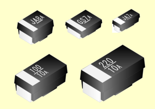
Resistors can fail open or short, alongside their value changing under environmental conditions and outside performance limits. Examples of resistor failures include:
Manufacturing defects causing intermittent problems. For example, improperly crimped caps on carbon or metal resistors can loosen and lose contact, and the resistor-to-cap resistance can change the values of the resistor[2]
Surface-mount resistors delaminating where dissimilar materials join, like between the ceramic substrate and the resistive layer.[21]
Nichrome thin-film resistors in integrated circuits attacked by phosphorus from the passivation glass, corroding them and increasing their resistance.[22]
SMD resistors with silver metallization of contacts suffering open-circuit failure in a sulfur-rich environment, due to buildup of silver sulfide.[6]
Copper dendrites growing from Copper(II) oxide present in some materials (like the layer facilitating adhesion of metallization to a ceramic substrate) and bridging the trimming kerf slot.[3]
Potentiometers and trimmers
Potentiometers and trimmers are three-terminal electromechanical parts, containing a resistive path with an adjustable wiper contact. Along with the failure modes for normal resistors, mechanical wear on the wiper and the resistive layer, corrosion, surface contamination, and mechanical deformations may lead to intermittent path-wiper resistance changes, which are a problem with audio amplifiers. Many types are not perfectly sealed, with contaminants and moisture entering the part; an especially common contaminant is the solder flux. Mechanical deformations (like an impaired wiper-path contact) can occur by housing warpage during soldering or mechanical stress during mounting. Excess stress on leads can cause substrate cracking and open failure when the crack penetrates the resistive path.[2]
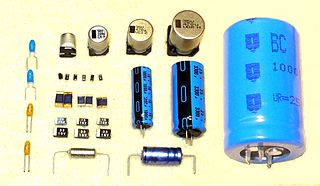
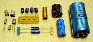
Capacitors are characterized by their capacitance, parasitic resistance in series and parallel, breakdown voltage and dissipation factor; both parasitic parameters are often frequency- and voltage-dependent. Structurally, capacitors consist of electrodes separated by a dielectric, connecting leads, and housing; deterioration of any of these may cause parameter shifts or failure. Shorted failures and leakage due to increase of parallel parasitic resistance are the most common failure modes of capacitors, followed by open failures.[citation needed] Some examples of capacitor failures include:
Dielectric breakdown due to overvoltage or aging of the dielectric, occurring when breakdown voltage falls below operating voltage. Some types of capacitors "self-heal", as internal arcing vaporizes parts of the electrodes around the failed spot. Others form a conductive pathway through the dielectric, leading to shorting or partial loss of dielectric resistance.[2]
Electrode materials migrating across the dielectric, forming conductive paths.[2]
Leads separated from the capacitor by rough handling during storage, assembly or operation, leading to an open failure. The failure can occur invisibly inside the packaging and is measurable.[2]
Increase of dissipation factor due to contamination of capacitor materials, particularly from flux and solvent residues.[2]
Electrolytic capacitors
In addition to the problems listed above, electrolytic capacitors suffer from these failures:
Aluminium versions having their electrolyte dry out for a gradual leakage, equivalent series resistance and loss of capacitance. Power dissipation by high ripple currents and internal resistances cause an increase of the capacitor's internal temperature beyond specifications, accelerating the deterioration rate; such capacitors usually fail short.[2]
Electrolyte contamination (like from moisture) corroding the electrodes, leading to capacitance loss and shorts.[2]
Electrolytes evolving a gas, increasing pressure inside the capacitor housing and sometimes causing an explosion; an example is the capacitor plague.[citation needed]
Tantalum versions being electrically overstressed, permanently degrading the dielectric and sometimes causing open or short failure.[2] Sites that have failed this way are usually visible as a discolored dielectric or as a locally melted anode.[6]
Metal oxide varistors typically have lower resistance as they heat up; if connected directly across a power bus, for protection against voltage spikes, a varistor with a lowered trigger voltage can slide into catastrophic thermal runaway and sometimes a small explosion or fire.[23] To prevent this, the fault current is typically limited by a thermal fuse, circuit breaker, or other current limiting device.
Stiction causing moving parts to stick; an external impulse sometimes restores functionality. Non-stick coatings, reduction of contact area, and increased awareness mitigate the problem in contemporary systems.[9]
Particles migrating in the system and blocking their movements. Conductive particles may short out circuits like electrostatic actuators. Wear damages the surfaces and releases debris that can be a source of particle contamination.
Dielectric charging leading to change of functionality and at some point parameter failures.[24]
Recreating failure modes
In order to reduce failures, a precise knowledge of bond strength quality measurement during product design and subsequent manufacture is of vital importance. The best place to start is with the failure mode. This is based on the assumption that there is a particular failure mode, or range of modes, that may occur within a product. It is therefore reasonable to assume that the bond test should replicate the mode, or modes of interest. However, exact replication is not always possible. The test load must be applied to some part of the sample and transferred through the sample to the bond. If this part of the sample is the only option and is weaker than the bond itself, the sample will fail before the bond.[25]
A transistor is a semiconductor device used to amplify or switch electrical signals and power. It is one of the basic building blocks of modern electronics. It is composed of semiconductor material, usually with at least three terminals for connection to an electronic circuit. A voltage or current applied to one pair of the transistor's terminals controls the current through another pair of terminals. Because the controlled (output) power can be higher than the controlling (input) power, a transistor can amplify a signal. Some transistors are packaged individually, but many more in miniature form are found embedded in integrated circuits. Because transistors are the key active components in practically all modern electronics, many people consider them one of the 20th century's greatest inventions.
The metal–oxide–semiconductor field-effect transistor is a type of field-effect transistor (FET), most commonly fabricated by the controlled oxidation of silicon. It has an insulated gate, the voltage of which determines the conductivity of the device. This ability to change conductivity with the amount of applied voltage can be used for amplifying or switching electronic signals. The term metal–insulator–semiconductor field-effect transistor (MISFET) is almost synonymous with MOSFET. Another near-synonym is insulated-gate field-effect transistor (IGFET).
A printed circuit board (PCB), also called printed wiring board (PWB), is a medium used to connect or "wire" components to one another in a circuit. It takes the form of a laminated sandwich structure of conductive and insulating layers: each of the conductive layers is designed with a pattern of traces, planes and other features etched from one or more sheet layers of copper laminated onto and/or between sheet layers of a non-conductive substrate. Electrical components may be fixed to conductive pads on the outer layers in the shape designed to accept the component's terminals, generally by means of soldering, to both electrically connect and mechanically fasten them to it. Another manufacturing process adds vias, plated-through holes that allow interconnections between layers.
Electrostatic discharge (ESD) is a sudden and momentary flow of electric current between two differently-charged objects when brought close together or when the dielectric between them breaks down, often creating a visible spark associated with the static electricity between the objects.
An electrolytic capacitor is a polarized capacitor whose anode or positive plate is made of a metal that forms an insulating oxide layer through anodization. This oxide layer acts as the dielectric of the capacitor. A solid, liquid, or gel electrolyte covers the surface of this oxide layer, serving as the cathode or negative plate of the capacitor. Because of their very thin dielectric oxide layer and enlarged anode surface, electrolytic capacitors have a much higher capacitance-voltage (CV) product per unit volume than ceramic capacitors or film capacitors, and so can have large capacitance values. There are three families of electrolytic capacitor: aluminium electrolytic capacitors, tantalum electrolytic capacitors, and niobium electrolytic capacitors.
An antifuse is an electrical device that performs the opposite function to a fuse. Whereas a fuse starts with a low resistance and is designed to permanently break or open an electrically conductive path, an antifuse starts with a high resistance--an open circuit--and programming it converts it into a permanent electrically conductive path. This technology has many applications. Antifuses are best known for their use in mini-light style low-voltage Christmas tree lights.
An electronic component is any basic discrete electronic device or physical entity part of an electronic system used to affect electrons or their associated fields. Electronic components are mostly industrial products, available in a singular form and are not to be confused with electrical elements, which are conceptual abstractions representing idealized electronic components and elements. A datasheet for an electronic component is a technical document that provides detailed information about the component's specifications, characteristics, and performance.
Capacitors are manufactured in many styles, forms, dimensions, and from a large variety of materials. They all contain at least two electrical conductors, called plates, separated by an insulating layer (dielectric). Capacitors are widely used as parts of electrical circuits in many common electrical devices.
An ohmic contact is a non-rectifying electrical junction: a junction between two conductors that has a linear current–voltage (I–V) curve as with Ohm's law. Low-resistance ohmic contacts are used to allow charge to flow easily in both directions between the two conductors, without blocking due to rectification or excess power dissipation due to voltage thresholds.
In electrical engineering, a capacitor is a device that stores electrical energy by accumulating electric charges on two closely spaced surfaces that are insulated from each other. The capacitor was originally known as the condenser, a term still encountered in a few compound names, such as the condenser microphone. It is a passive electronic component with two terminals.
A ceramic capacitor is a fixed-value capacitor where the ceramic material acts as the dielectric. It is constructed of two or more alternating layers of ceramic and a metal layer acting as the electrodes. The composition of the ceramic material defines the electrical behavior and therefore applications. Ceramic capacitors are divided into two application classes:
A tantalum electrolytic capacitor is an electrolytic capacitor, a passive component of electronic circuits. It consists of a pellet of porous tantalum metal as an anode, covered by an insulating oxide layer that forms the dielectric, surrounded by liquid or solid electrolyte as a cathode. Because of its very thin and relatively high permittivity dielectric layer, the tantalum capacitor distinguishes itself from other conventional and electrolytic capacitors in having high capacitance per volume and lower weight.
In electronics, leakage is the gradual transfer of electrical energy across a boundary normally viewed as insulating, such as the spontaneous discharge of a charged capacitor, magnetic coupling of a transformer with other components, or flow of current across a transistor in the "off" state or a reverse-polarized diode.
In electrical networks, a parasitic element is a circuit element that is possessed by an electrical component but which it is not desirable for it to have for its intended purpose. For instance, a resistor is designed to possess resistance, but will also possess unwanted parasitic capacitance.
A polymer capacitor, or more accurately a polymer electrolytic capacitor, is an electrolytic capacitor (e-cap) with a solid conductive polymer electrolyte. There are four different types:
Film capacitors, plastic film capacitors, film dielectric capacitors, or polymer film capacitors, generically called film caps as well as power film capacitors, are electrical capacitors with an insulating plastic film as the dielectric, sometimes combined with paper as carrier of the electrodes.
The field-effect transistor (FET) is a type of transistor that uses an electric field to control the flow of current in a semiconductor. It comes in two types: junction FET (JFET) and metal-oxide-semiconductor FET (MOSFET). FETs have three terminals: source, gate, and drain. FETs control the flow of current by the application of a voltage to the gate, which in turn alters the conductivity between the drain and source.
Aluminum electrolytic capacitors are polarized electrolytic capacitors whose anode electrode (+) is made of a pure aluminum foil with an etched surface. The aluminum forms a very thin insulating layer of aluminum oxide by anodization that acts as the dielectric of the capacitor. A non-solid electrolyte covers the rough surface of the oxide layer, serving in principle as the second electrode (cathode) (-) of the capacitor. A second aluminum foil called "cathode foil" contacts the electrolyte and serves as the electrical connection to the negative terminal of the capacitor.
A niobium electrolytic capacitor is an electrolytic capacitor whose anode (+) is made of passivated niobium metal or niobium monoxide, on which an insulating niobium pentoxide layer acts as a dielectric. A solid electrolyte on the surface of the oxide layer serves as the capacitor's cathode (−).
↑ Herfst, R.W., Steeneken, P.G., Schmitz, J., Time and voltage dependence of dielectric charging in RF MEMS capacitive switches, (2007) Annual Proceedings – Reliability Physics (Symposium), art. no. 4227667, pp. 417–421.
↑ Sykes, Bob (June 2010). "Why test bonds?". Global SMT & Packaging magazine. Archived from the original on 3 July 2018. Retrieved 20 June 2014.
Further reading
Herfst, R.W., Steeneken, P.G., Schmitz, J., Time and voltage dependence of dielectric charging in RF MEMS capacitive switches, (2007) Annual Proceedings – Reliability Physics (Symposium), art. no. 4227667, pp. 417–421.
This page is based on this Wikipedia article Text is available under the CC BY-SA 4.0 license; additional terms may apply. Images, videos and audio are available under their respective licenses.