In signal processing, group delay and phase delay are two related ways of describing how a signal's frequency components are delayed in time when passing through a linear time-invariant (LTI) system. Phase delay describes the time shift of a sinusoidal component. Group delay describes the time shift of the envelope of a wave packet, a "pack" or "group" of oscillations centered around one frequency that travel together, formed for instance by multiplying a sine wave by an envelope.

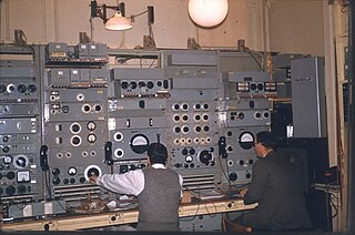
In electrical engineering, a transmission line is a specialized cable or other structure designed to conduct electromagnetic waves in a contained manner. The term applies when the conductors are long enough that the wave nature of the transmission must be taken into account. This applies especially to radio-frequency engineering because the short wavelengths mean that wave phenomena arise over very short distances. However, the theory of transmission lines was historically developed to explain phenomena on very long telegraph lines, especially submarine telegraph cables.

In electrical engineering, the input impedance of an electrical network is the measure of the opposition to current (impedance), both static (resistance) and dynamic (reactance), into a load network that is external to the electrical source network. The input admittance is a measure of the load network's propensity to draw current. The source network is the portion of the network that transmits power, and the load network is the portion of the network that consumes power.
An all-pass filter is a signal processing filter that passes all frequencies equally in gain, but changes the phase relationship among various frequencies. Most types of filter reduce the amplitude of the signal applied to it for some values of frequency, whereas the all-pass filter allows all frequencies through without changes in level.

Electronic filter topology defines electronic filter circuits without taking note of the values of the components used but only the manner in which those components are connected.

An analog delay line is a network of electrical components connected in cascade, where each individual element creates a time difference between its input and output. It operates on analog signals whose amplitude varies continuously. In the case of a periodic signal, the time difference can be described in terms of a change in the phase of the signal. One example of an analog delay line is a bucket-brigade device.
Zobel networks are a type of filter section based on the image-impedance design principle. They are named after Otto Zobel of Bell Labs, who published a much-referenced paper on image filters in 1923. The distinguishing feature of Zobel networks is that the input impedance is fixed in the design independently of the transfer function. This characteristic is achieved at the expense of a much higher component count compared to other types of filter sections. The impedance would normally be specified to be constant and purely resistive. For this reason, Zobel networks are also known as constant resistance networks. However, any impedance achievable with discrete components is possible.
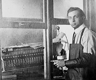
Otto Julius Zobel was an electrical engineer who worked for the American Telephone & Telegraph Company (AT&T) in the early part of the 20th century. Zobel's work on filter design was revolutionary and led, in conjunction with the work of John R. Carson, to significant commercial advances for AT&T in the field of frequency-division multiplex (FDM) telephone transmissions.

A lattice phase equaliser or lattice filter is an example of an all-pass filter. That is, the attenuation of the filter is constant at all frequencies but the relative phase between input and output varies with frequency. The lattice filter topology has the particular property of being a constant-resistance network and for this reason is often used in combination with other constant-resistance filters such as bridge-T equalisers. The topology of a lattice filter, also called an X-section, is identical to bridge topology. The lattice phase equaliser was invented by Otto Zobel using a filter topology proposed by George Campbell.

The bridged-T delay equaliser is an electrical all-pass filter circuit utilising bridged-T topology whose purpose is to insert an (ideally) constant delay at all frequencies in the signal path. It is a class of image filter.
Constant k filters, also k-type filters, are a type of electronic filter designed using the image method. They are the original and simplest filters produced by this methodology and consist of a ladder network of identical sections of passive components. Historically, they are the first filters that could approach the ideal filter frequency response to within any prescribed limit with the addition of a sufficient number of sections. However, they are rarely considered for a modern design, the principles behind them having been superseded by other methodologies which are more accurate in their prediction of filter response.
m-derived filters or m-type filters are a type of electronic filter designed using the image method. They were invented by Otto Zobel in the early 1920s. This filter type was originally intended for use with telephone multiplexing and was an improvement on the existing constant k type filter. The main problem being addressed was the need to achieve a better match of the filter into the terminating impedances. In general, all filters designed by the image method fail to give an exact match, but the m-type filter is a big improvement with suitable choice of the parameter m. The m-type filter section has a further advantage in that there is a rapid transition from the cut-off frequency of the passband to a pole of attenuation just inside the stopband. Despite these advantages, there is a drawback with m-type filters; at frequencies past the pole of attenuation, the response starts to rise again, and m-types have poor stopband rejection. For this reason, filters designed using m-type sections are often designed as composite filters with a mixture of k-type and m-type sections and different values of m at different points to get the optimum performance from both types.

A phase shift module is a microwave network module which provides a controllable phase shift of the RF signal. Phase shifters are used in phased arrays.
An equivalent impedance is an equivalent circuit of an electrical network of impedance elements which presents the same impedance between all pairs of terminals as did the given network. This article describes mathematical transformations between some passive, linear impedance networks commonly found in electronic circuits.
A constant-resistance network in electrical engineering is a network whose input resistance does not change with frequency when correctly terminated. Examples of constant resistance networks include:
Analogue filters are a basic building block of signal processing much used in electronics. Amongst their many applications are the separation of an audio signal before application to bass, mid-range, and tweeter loudspeakers; the combining and later separation of multiple telephone conversations onto a single channel; the selection of a chosen radio station in a radio receiver and rejection of others.

Metamaterial antennas are a class of antennas which use metamaterials to increase performance of miniaturized antenna systems. Their purpose, as with any electromagnetic antenna, is to launch energy into free space. However, this class of antenna incorporates metamaterials, which are materials engineered with novel, often microscopic, structures to produce unusual physical properties. Antenna designs incorporating metamaterials can step-up the antenna's radiated power.
In telecommunication, equalization is the reversal of distortion incurred by a signal transmitted through a channel. Equalizers are used to render the frequency response—for instance of a telephone line—flat from end-to-end. When a channel has been equalized the frequency domain attributes of the signal at the input are faithfully reproduced at the output. Telephones, DSL lines and television cables use equalizers to prepare data signals for transmission.
A symmetrical lattice is a two-port electrical wave filter in which diagonally-crossed shunt elements are present – a configuration which sets it apart from ladder networks. The component arrangement of the lattice is shown in the diagram below. The filter properties of this circuit were first developed using image impedance concepts, but later the more general techniques of network analysis were applied to it.
Lattice and bridged-T equalizers are circuits which are used to correct for the amplitude and/or phase errors of a network or transmission line. Usually, the aim is to achieve an overall system performance with a flat amplitude response and constant delay over a prescribed frequency range, by the addition of an equalizer. In the past, designers have used a variety of techniques to realize their equalizer circuits. These include the method of complementary networks; the method of straight line asymptotes; using a purpose built test-jig; the use of standard circuit building blocks,; or with the aid of computer programs. In addition, trial and error methods have been found to be surprisingly effective, when performed by an experienced designer.
