An audio induction loop system (also called an audio-frequency induction loop or AFIL, or a hearing loop [1] ) is an assistive listening device for individuals with reduced ranges of hearing. [2]
An audio induction loop system (also called an audio-frequency induction loop or AFIL, or a hearing loop [1] ) is an assistive listening device for individuals with reduced ranges of hearing. [2]
The first patented magnetic induction loop communication system was invented by Joseph Poliakoff (grandfather of Sir Martyn Poliakoff) in Great Britain in 1937. [3] [4] [5]
The pickup coil in a hearing aid is known as a telecoil (or T-coil) because its early form was to pick up a magnetic field from coils within a telephone. These were included as a part of the method of enabling a two-way conversation over a single pair of wires. The telecoil enabled the hearing aid user to hear the phone conversation clearly without picking up background noise.
From this, the natural development was to generate electromagnetic fields representing the audio, which the telecoil could receive.
A hearing loop consists of one or more physical loops of cable which are placed around a designated area, usually a room or a building. The cable generates an electromagnetic field throughout the looped space which can be picked up by a telecoil-equipped hearing aid, a cochlear implant (CI) processor, or a specialized hand-held hearing loop receiver for individuals without telecoil-compatible hearing aids.
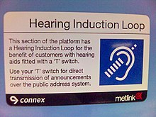
The loops carry baseband audio-frequency currents; no carrier signal is used. The benefit is that it allows the sound source of interest –whether a musical performance or a ticket taker's side of the conversation –to be transmitted to the hearing-impaired listener clearly and free of other distracting noise in the environment. [6] Typical installation sites include concert halls, ticket kiosks, high-traffic public buildings (for PA announcements), auditoriums, places of worship, courtrooms, meeting rooms, and homes. [7]
The simplest form of AFIL is a single wire around a room, driven from a power amplifier as a loudspeaker would be driven. The coupling of magnetic fields is described mathematically by Faraday's law of induction.
A basic AFIL using a general purpose amplifier has some disadvantages. The loop driver amplifier requires some additional circuits to overcome these. Using anything other than a correctly designed loop driver amplifier is not only unsatisfactory, but may result in a loop installation that can generate harmonics when driven into distortion, and these will cause radio interference. This must be prevented, both for sound quality and for legal reasons as it is illegal to cause such interference in these circumstances. In Europe, the EMC Directive applies, and it is also illegal to supply or install unsuitable electronic and electrical equipment. [8]
A second factor is that many forms of hearing impairment mean that sound levels must be kept fairly constant. An effective loop driver will have an automatic level control to compress the signal, providing a constant loop amplitude for a wide range of source levels. Meeting this requirement is likely to meet the interference requirement at the same time. To do this, the loop driver should give constant output for at least 30 dB input range.
A third problem is the inductance of the loop cable, and its effect upon the higher frequencies of sound. To overcome this, many loop drivers operate as current mode amplifiers instead of voltage mode. By setting the amplifier characteristic between voltage and current mode, the overall performance is optimised for good bandwidth with minimum distortion. There are other options for reducing the effect of cable inductance, including the use of a multi-core cable where the conductors are connected in parallel.
Structural steel and other metalwork in buildings can cause problems by reducing the field strength unevenly across the loop area, causing frequency distortions. In most cases, a solution can be found using combinations of loops with phase shift between them, combined with frequency correction and increased signal strength.[ citation needed ]
Audio induction loops create relatively high magnetic field levels. Other equipment must be designed and installed to work properly within this field.
The most common cause of problems is earth loops, where different pieces of equipment are connected together by signal wires, but powered from different power sockets in different parts of the room or building. The combination of the mains earth and signal earth creates a receiving loop that produces an interference signal proportional to the area within the earth loop. [9] Various steps are used to prevent interference on audio and video equipment. Powering signal sources and output devices from the same mains circuit to prevent formation of an earth loop; shielded cables or signal isolators may be used.
An objective of the field strength requirements of standards for AFILs is to make the perceived loudness of sound from the loop the same as from the microphone in the hearing aid. This is the basis of the average field strength of 100mA/m used to generate today's performance standards around the world. [10]
IEC 60118-4 (formerly Britain's BS 6083 part 4, also known as EN 60118-4) is now the main specification for international use. [11] This standard specifies long term average field strength with allowance for program peaks, background noise level, and frequency response.
IEC 62489-1 specifies how to measure the performance of the system components in a hearing loop system. The standard recommends fixed and portable monitoring devices to allow verification of the proper operation of the hearing loop.
BS 7594 (published by the BSI and widely used in Britain) is a non-mandatory guideline for the design and installation of induction loops. It has a comprehensive guide to theory, as well as guidance for those considering the installation of AFILs in buildings for which they may be responsible. It also contains some valuable guidance relating to other equipment within the loop area. The calibration of field strength measuring devices is also included.
In the United Kingdom, as an aid for disability, their provision, where reasonably possible, is required by the Equality Act 2010 and previously by the Disability Discrimination Act 1995, [12] and they are available in "the back seats of all London taxis, which have a little microphone embedded in the dashboard in front of the driver; at 18,000 post offices in the U.K.; at most churches and cathedrals", according to Prof. David G. Myers. [7]
In the United States, an alternative technology using FM transmission to "neck loop" receivers was more widely adopted due to economic advantages. In comparison, hearing loop systems require a greater initial investment by the facility operator, but offer greater convenience and avoid the social stigma and hygienic concerns entailed by the FM system's paraphernalia for those who have hearing aids. [7]
Another alternative system, used primarily in theatres, uses invisible infrared radiation; compatible headsets can pick up the modulated infrared energy to reproduce sound.

An electromagnetic coil is an electrical conductor such as a wire in the shape of a coil. Electromagnetic coils are used in electrical engineering, in applications where electric currents interact with magnetic fields, in devices such as electric motors, generators, inductors, electromagnets, transformers, sensor coils such as in medical MRI imaging machines. Either an electric current is passed through the wire of the coil to generate a magnetic field, or conversely, an external time-varying magnetic field through the interior of the coil generates an EMF (voltage) in the conductor.

In telecommunications and professional audio, a balanced line or balanced signal pair is an electrical circuit consisting of two conductors of the same type, both of which have equal impedances along their lengths, to ground, and to other circuits. The primary advantage of the balanced line format is good rejection of common-mode noise and interference when fed to a differential device such as a transformer or differential amplifier.

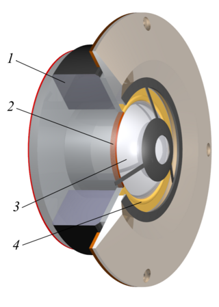
A loudspeaker is a combination of one or more speaker drivers, an enclosure, and electrical connections. The speaker driver is an electroacoustic transducer that converts an electrical audio signal into a corresponding sound.
A tweeter or treble speaker is a special type of loudspeaker that is designed to produce high audio frequencies, typically up to 100 kHz. The name is derived from the high pitched sounds made by some birds (tweets), especially in contrast to the low woofs made by many dogs, after which low-frequency drivers are named (woofers).
A woofer or bass speaker is a technical term for a loudspeaker driver designed to produce low frequency sounds, typically from 20 Hz up to a few hundred Hz. The name is from the onomatopoeic English word for a dog's deep bark, "woof". The most common design for a woofer is the electrodynamic driver, which typically uses a stiff paper cone, driven by a voice coil surrounded by a magnetic field.

Headphones are a pair of small loudspeaker drivers worn on or around the head over a user's ears. They are electroacoustic transducers, which convert an electrical signal to a corresponding sound. Headphones let a single user listen to an audio source privately, in contrast to a loudspeaker, which emits sound into the open air for anyone nearby to hear. Headphones are also known as earphones or, colloquially, cans. Circumaural and supra-aural headphones use a band over the top of the head to hold the drivers in place. Another type, known as earbuds or earpieces, consists of individual units that plug into the user's ear canal; within that category have been developed cordless air buds using wireless technology. A third type are bone conduction headphones, which typically wrap around the back of the head and rest in front of the ear canal, leaving the ear canal open. In the context of telecommunication, a headset is a combination of a headphone and microphone.
Balanced audio is a method of interconnecting audio equipment using balanced interfaces. This type of connection is very important in sound recording and production because it allows the use of long cables while reducing susceptibility to external noise caused by electromagnetic interference. The balanced interface guarantees that induced noise appears as common-mode voltages at the receiver which can be rejected by a differential device.
This is an index of articles relating to electronics and electricity or natural electricity and things that run on electricity and things that use or conduct electricity.

A balun is an electrical device that allows balanced and unbalanced lines to be interfaced without disturbing the impedance arrangement of either line. A balun can take many forms and may include devices that also transform impedances but need not do so. Sometimes, in the case of transformer baluns, they use magnetic coupling but need not do so. Common-mode chokes are also used as baluns and work by eliminating, rather than rejecting, common mode signals.

Audio system measurements are used to quantify audio system performance. These measurements are made for several purposes. Designers take measurements to specify the performance of a piece of equipment. Maintenance engineers make them to ensure equipment is still working to specification, or to ensure that the cumulative defects of an audio path are within limits considered acceptable. Audio system measurements often accommodate psychoacoustic principles to measure the system in a way that relates to human hearing.

A hearing aid is a device designed to improve hearing by making sound audible to a person with hearing loss. Hearing aids are classified as medical devices in most countries, and regulated by the respective regulations. Small audio amplifiers such as personal sound amplification products (PSAPs) or other plain sound reinforcing systems cannot be sold as "hearing aids".
In an electrical system, a ground loop or earth loop occurs when two points of a circuit are intended to have the same ground reference potential but instead have a different potential between them. This is typically caused when enough current is flowing in the connection between the two ground points to produce a voltage drop and cause the two points to be at different potentials. Current may be produced in a ground loop by electromagnetic induction.
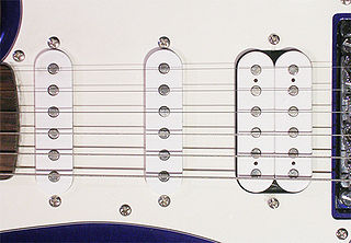
A pickup is an electronic device that converts energy from one form to another that captures or senses mechanical vibrations produced by musical instruments, particularly stringed instruments such as the electric guitar, and converts these to an electrical signal that is amplified using an instrument amplifier to produce musical sounds through a loudspeaker in a speaker enclosure. The signal from a pickup can also be recorded directly.
An induction or inductive loop is an electromagnetic communication or detection system which uses a moving magnet or an alternating current to induce an electric current in a nearby wire. Induction loops are used for transmission and reception of communication signals, or for detection of metal objects in metal detectors or vehicle presence indicators. A common modern use for induction loops is to provide hearing assistance to hearing-aid users.
Mains hum, electric hum, cycle hum, or power line hum is a sound associated with alternating current which is twice the frequency of the mains electricity. The fundamental frequency of this sound is usually double that of fundamental 50/60 Hz, i.e., 100/120 Hz, depending on the local power-line frequency. The sound often has heavy harmonic content above 50/60 Hz. Because of the presence of mains current in mains-powered audio equipment as well as ubiquitous AC electromagnetic fields from nearby appliances and wiring, 50/60 Hz electrical noise can get into audio systems, and is heard as mains hum from their speakers. Mains hum may also be heard coming from powerful electric power grid equipment such as utility transformers, caused by mechanical vibrations induced by magnetostriction in magnetic core. Onboard aircraft the frequency heard is often higher pitched, due to the use of 400 Hz AC power in these settings because 400 Hz transformers are much smaller and lighter.

Powered speakers, also known as self-powered speakers and active speakers, are loudspeakers that have built-in amplifiers. Powered speakers are used in a range of settings, including in sound reinforcement systems, both for the main speakers facing the audience and the monitor speakers facing the performers; by DJs performing at dance events and raves; in private homes as part of hi-fi or home cinema audio systems and as computer speakers. They can be connected directly to a mixing console or other low-level audio signal source without the need for an external amplifier. Some active speakers designed for sound reinforcement system use have an onboard mixing console and microphone preamplifier, which enables microphones to be connected directly to the speaker.

Various types of electrical transformer are made for different purposes. Despite their design differences, the various types employ the same basic principle as discovered in 1831 by Michael Faraday, and share several key functional parts.

An electrodynamic speaker driver, often called simply a speaker driver when the type is implicit, is an individual transducer that converts an electrical audio signal to sound waves. While the term is sometimes used interchangeably with the term speaker (loudspeaker), it is usually applied to specialized transducers that reproduce only a portion of the audible frequency range, or to the one or more drivers within a loudspeaker cabinet. For high fidelity reproduction of sound, multiple loudspeakers are often mounted in the same enclosure, each reproducing a different part of the audible frequency range. In this case the individual speakers are referred to as drivers and the entire unit is called a loudspeaker. Drivers made for reproducing high audio frequencies are called tweeters, those for middle frequencies are called mid-range drivers, and those for low frequencies are called woofers, while those for very low bass range are subwoofers. Less common types of drivers are supertweeters and rotary woofers.
This glossary of electrical and electronics engineering is a list of definitions of terms and concepts related specifically to electrical engineering and electronics engineering. For terms related to engineering in general, see Glossary of engineering.