
A fluid flowing around an object exerts a force on it. Lift is the component of this force that is perpendicular to the oncoming flow direction. It contrasts with the drag force, which is the component of the force parallel to the flow direction. Lift conventionally acts in an upward direction in order to counter the force of gravity, but it can act in any direction at right angles to the flow.

In fluid dynamics, laminar flow is characterized by fluid particles following smooth paths in layers, with each layer moving smoothly past the adjacent layers with little or no mixing. At low velocities, the fluid tends to flow without lateral mixing, and adjacent layers slide past one another like playing cards. There are no cross-currents perpendicular to the direction of flow, nor eddies or swirls of fluids. In laminar flow, the motion of the particles of the fluid is very orderly with particles close to a solid surface moving in straight lines parallel to that surface. Laminar flow is a flow regime characterized by high momentum diffusion and low momentum convection.

A wing is a type of fin that produces lift while moving through air or some other fluid. Accordingly, wings have streamlined cross-sections that are subject to aerodynamic forces and act as airfoils. A wing's aerodynamic efficiency is expressed as its lift-to-drag ratio. The lift a wing generates at a given speed and angle of attack can be one to two orders of magnitude greater than the total drag on the wing. A high lift-to-drag ratio requires a significantly smaller thrust to propel the wings through the air at sufficient lift.
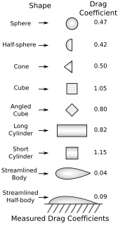
In fluid dynamics, the drag coefficient is a dimensionless quantity that is used to quantify the drag or resistance of an object in a fluid environment, such as air or water. It is used in the drag equation in which a lower drag coefficient indicates the object will have less aerodynamic or hydrodynamic drag. The drag coefficient is always associated with a particular surface area.

In physics and fluid mechanics, a boundary layer is the thin layer of fluid in the immediate vicinity of a bounding surface formed by the fluid flowing along the surface. The fluid's interaction with the wall induces a no-slip boundary condition. The flow velocity then monotonically increases above the surface until it returns to the bulk flow velocity. The thin layer consisting of fluid whose velocity has not yet returned to the bulk flow velocity is called the velocity boundary layer.
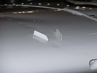
A vortex generator (VG) is an aerodynamic device, consisting of a small vane usually attached to a lifting surface or a rotor blade of a wind turbine. VGs may also be attached to some part of an aerodynamic vehicle such as an aircraft fuselage or a car. When the airfoil or the body is in motion relative to the air, the VG creates a vortex, which, by removing some part of the slow-moving boundary layer in contact with the airfoil surface, delays local flow separation and aerodynamic stalling, thereby improving the effectiveness of wings and control surfaces, such as flaps, elevators, ailerons, and rudders.

An airfoil or aerofoil is the cross-sectional shape of an object whose motion through a gas is capable of generating significant lift, such as a wing, a sail, or the blades of propeller, rotor, or turbine.

Parasitic drag, also known as profile drag, is a type of aerodynamic drag that acts on any object when the object is moving through a fluid. Parasitic drag is a combination of form drag and skin friction drag. It affects all objects regardless of whether they are capable of generating lift.

In aircraft design and aerospace engineering, a high-lift device is a component or mechanism on an aircraft's wing that increases the amount of lift produced by the wing. The device may be a fixed component, or a movable mechanism which is deployed when required. Common movable high-lift devices include wing flaps and slats. Fixed devices include leading-edge slots, leading edge root extensions, and boundary layer control systems.
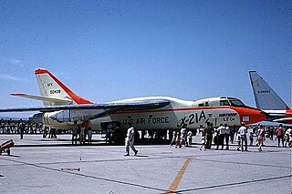
The Northrop X-21A was an experimental aircraft designed to test wings with laminar flow control. It was based on the Douglas WB-66D airframe, with the wing-mounted engines moved to the rear fuselage and making space for air compressors. The aircraft first flew on 18 April 1963 with NASA test pilot Jack Wells at the controls. Although useful testing was accomplished, the extensive maintenance of the intricate laminar-flow system caused the end of the program.

A leading-edge cuff is a fixed aerodynamic wing device employed on fixed-wing aircraft to improve the stall and spin characteristics. Cuffs may be either factory-designed or an after-market add-on modification.

A supercritical airfoil is an airfoil designed primarily to delay the onset of wave drag in the transonic speed range.

A turbulator is a device that turns a laminar boundary layer into a turbulent boundary layer.

The Gurney flap is a small tab projecting from the trailing edge of a wing. Typically it is set at a right angle to the pressure-side surface of the airfoil and projects 1% to 2% of the wing chord. This trailing edge device can improve the performance of a simple airfoil to nearly the same level as a complex high-performance design.

Vortex lift is that portion of lift due to the action of leading edge vortices. It is generated by wings with highly sweptback, sharp, leading edges or highly-swept wing-root extensions added to a wing of moderate sweep. It is sometimes known as non-linear lift due to its rapid increase with angle of attack. and controlled separation lift, to distinguish it from conventional lift which occurs with attached flow.
Boundary layer control refers to methods of controlling the behaviour of fluid flow boundary layers.

In fluid dynamics, flow separation or boundary layer separation is the detachment of a boundary layer from a surface into a wake.

Eastman Jacobs (1902–1987) was a leading aerodynamicist who worked for NACA's Langley Memorial Aeronautical Laboratory from the 1920s to the 1940s. He was responsible for advancing many fields in aerodynamics, dealing particularly with wind tunnels, airfoils, turbulence, boundary layers, and Schlieren photography.

Flow control is a major rapidly-evolving field of fluid dynamics. It implies a small change of a configuration serving an ideally large engineering benefit, like drag reduction, lift increase, mixing enhancement or noise reduction. This change may be accomplished by passive or active devices. Passive devices, like turbulators or roughness elements, are steady and require no energy by definition. Active control requires actuators that may be driven in a time-dependent manner and require energy. Examples are valves and plasma actuators. The actuation command may be pre-determined or be dependent on sensors monitoring the flow state.
Sweeping jet actuators are a type of active flow control technology based on fluidic oscillators used to produce sweeping jets. The first use of fluidic oscillators in the form of sweeping jets for flow control was demonstrated by Raman et al., 1999.<Cavity Resonance Suppression Using Miniature Fluidic Oscillators, G. Raman, S. Raghu and T.J. Bencic' AIAA-99-1900, 5th AIAA/CEAS Aeroacoustics Conference, Seattle, WA, May 10–12, 1999> and later by several authors working in the area of flow control. Many organizations have been working on the use of such actuators for flow control. Boeing, NASA and the University of Arizona Department of Aerospace and Mechanical Engineering, Illinois Institute of Technology, [Advanced Fluidics], Technical University of Berlin are a few of them. They are slots built into the control surface of an airfoil that build on the same principles as that of blown flaps; that by actively blowing air over the surface of an airfoil the effective lift produced by it is increased.