In physics and fluid mechanics, a boundary layer is the thin layer of fluid in the immediate vicinity of a bounding surface formed by the fluid flowing along the surface. The fluid's interaction with the wall induces a no-slip boundary condition. The flow velocity then monotonically increases above the surface until it returns to the bulk flow velocity. The thin layer consisting of fluid whose velocity has not yet returned to the bulk flow velocity is called the velocity boundary layer.
An airfoil or aerofoil is a streamlined body that is capable of generating significantly more lift than drag. Wings, sails and propeller blades are examples of airfoils. Foils of similar function designed with water as the working fluid are called hydrofoils.

Parasitic drag, also known as profile drag, is a type of aerodynamic drag that acts on any object when the object is moving through a fluid. Parasitic drag is a combination of form drag and skin friction drag. It affects all objects regardless of whether they are capable of generating lift.

The Douglas B-66 Destroyer is a light bomber that was designed and produced by the American aviation manufacturer Douglas Aircraft Company.

The Northrop F-89 Scorpion is an all-weather, twin-engined interceptor aircraft designed and produced by the American aircraft manufacturer Northrop Corporation. It was the first jet-powered aircraft to be designed for the interceptor role from the outset to enter service, as well as the first combat aircraft to be armed with air-to-air nuclear weapons in the form of the unguided Genie rocket. The name Scorpion came from the aircraft's elevated tail unit and high-mounted horizontal stabilizer, which kept it clear of the engine exhaust.
The Northrop YF-17 was a prototype lightweight fighter aircraft designed by Northrop aviation for the United States Air Force's Lightweight Fighter (LWF) technology evaluation program. The LWF was initiated because many in the fighter community believed that aircraft like the F-15 Eagle were too large and expensive for many combat roles. The YF-17 was the culmination of a long line of Northrop designs, beginning with the N-102 Fang in 1956, continuing through the F-5 family.

Blown flaps, blown wing or jet flaps are powered aerodynamic high-lift devices used on the wings of certain aircraft to improve their low-speed flight characteristics. They use air blown through nozzles to shape the airflow over the rear edge of the wing, directing the flow downward to increase the lift coefficient. There are a variety of methods to achieve this airflow, most of which use jet exhaust or high-pressure air bled off of a jet engine's compressor and then redirected to follow the line of trailing-edge flaps.

The Yakovlev Yak-36, also known as Izdeliye V, is a Soviet technology demonstrator for a VTOL combat aircraft.
In the field of fluid dynamics the point at which the boundary layer changes from laminar to turbulent is called the transition point. Where and how this transition occurs depends on the Reynolds number, the pressure gradient, pressure fluctuations due to sound, surface vibration, the initial turbulence level of the flow, boundary layer suction, surface heat flows, and surface roughness. The effects of a boundary layer turned turbulent are an increase in drag due to skin friction. As speed increases, the upper surface transition point tends to move forward. As the angle of attack increases, the upper surface transition point also tends to move forward.

The Northrop XP-79, USAAF project number MX-365, was a rocket and jet-powered flying wing fighter aircraft, designed by Northrop. The pilot operated the aircraft in a prone position, permitting him to withstand much greater g-forces in pitch. It also used a welded magnesium monocoque structure instead of riveted aluminum.
The Lockheed CL-1200 Lancer was a late 1960s company-funded proposal for a fighter aircraft based on the Lockheed F-104 Starfighter. The CL-1200 was conceived and marketed mainly for and to non-US military services, as an export product. As such it would have competed with combat-proven designs like the Dassault Mirage III, McDonnell Douglas F-4 Phantom II, Mikoyan-Gurevich MiG-21, and Northrop F-5E Tiger II. The CL-1200 competed unsuccessfully against proposed fourth generation designs, under the US government's Lightweight Fighter program, which would eventually result in the General Dynamics F-16 and Northrop F-17 Cobra.

The General Dynamics F-16XL is a derivative of the F-16 Fighting Falcon with a cranked-arrow delta wing. It entered the United States Air Force's (USAF) Enhanced Tactical Fighter (ETF) competition in 1981 but lost to the F-15E Strike Eagle. The two prototypes were shelved until being turned over to NASA for additional aeronautical research in 1988. Both aircraft were fully retired in 2009 and stored at Edwards Air Force Base.
The Grumman G-118 was a design for an all-weather missile-armed interceptor aircraft for use on US Navy aircraft carriers. Originally conceived as an uprated F11F Tiger, it soon evolved into a larger and more powerful project. Although two prototypes were ordered in 1955, development was cancelled the same year in favor of the F4H Phantom II before any examples were built. Grumman's next carrier fighter would be the F-14 Tomcat, ordered in 1968.
In engineering, boundary layer control refers to methods of controlling the behaviour of fluid flow boundary layers.

The Armstrong Whitworth A.W.52 was an early flying wing aircraft designed and produced by British aircraft manufacturer Armstrong Whitworth Aircraft.
Boundary layer suction is a boundary layer control technique in which an air pump is used to extract the boundary layer at the wing or the inlet of an aircraft. Improving the air flow can reduce drag. Improvements in fuel efficiency have been estimated as high as 30%.

The SNCAC NC 1080 was a French jet-engined interceptor developed in the late 1940s by SNCAC for use aboard aircraft carriers. It was intended to compete for an Aéronavale contract and first flew in 1949. The aircraft used an innovative system of flight control surfaces that proved to be a failure during flight testing and had to be modified before it could fly again. Its development was troubled by other design flaws and the company's merger with SNCAN that same year. Further development was cancelled after a fatal crash destroyed the sole prototype in 1950.

The Lockheed XF-104 Starfighter was a single-engine, high-performance, supersonic interceptor prototype for a United States Air Force (USAF) series of lightweight and simple fighters. Only two aircraft were built; one aircraft was used primarily for aerodynamic research and the other served as an armament testbed, both aircraft being destroyed in accidents during testing. The XF-104s were forerunners of over 2,500 production Lockheed F-104 Starfighters.

The Rolls-Royce/Snecma Olympus 593 was an Anglo-French turbojet with reheat, which powered the supersonic airliner Concorde. It was initially a joint project between Bristol Siddeley Engines Limited (BSEL) and Snecma, derived from the Bristol Siddeley Olympus 22R engine. Rolls-Royce Limited acquired BSEL in 1966 during development of the engine, making BSEL the Bristol Engine Division of Rolls-Royce.
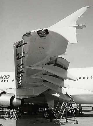
A slat is an aerodynamic surface on the leading edge of the wing of a fixed-wing aircraft. When retracted, the slat lies flush with the rest of the wing. A slat is deployed by sliding forward, opening a slot between the wing and the slat. Air from below the slat flows through the slot and replaces the boundary layer that has travelled at high speed around the leading edge of the slat, losing a significant amount of its kinetic energy due to skin friction drag. When deployed, slats allow the wings to operate at a higher angle of attack before stalling. With slats deployed an aircraft can fly at slower speeds, allowing it to take off and land in shorter distances. They are used during takeoff and landing and while performing low-speed maneuvers which may take the aircraft close to a stall. Slats are retracted in normal flight to minimize drag.