In electronics, the figures of merit of an amplifier are numerical measures that characterize its properties and performance. Figures of merit can be given as a list of specifications that include properties such as gain, bandwidth, noise and linearity, among others listed in this article. Figures of merit are important for determining the suitability of a particular amplifier for an intended use.

Bandwidth is the difference between the upper and lower frequencies in a continuous band of frequencies. It is typically measured in unit of hertz.
The decibel is a relative unit of measurement equal to one tenth of a bel (B). It expresses the ratio of two values of a power or root-power quantity on a logarithmic scale. Two signals whose levels differ by one decibel have a power ratio of 101/10 or root-power ratio of 101/20.

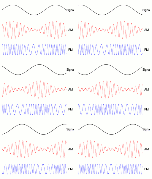
Frequency modulation (FM) is the encoding of information in a carrier wave by varying the instantaneous frequency of the wave. The technology is used in telecommunications, radio broadcasting, signal processing, and computing.

A weighting filter is used to emphasize or suppress some aspects of a phenomenon compared to others, for measurement or other purposes.
The symbol dBrn or dB(rn) is an abbreviation for decibels above reference noise.
In telecommunication, equivalent pulse code modulation (PCM) noise is the amount of noise power on a frequency-division multiplexing (FDM) or wire communication channel necessary to approximate the same judgment of speech quality created by quantization noise in a PCM channel.

Signal-to-noise ratio is a measure used in science and engineering that compares the level of a desired signal to the level of background noise. SNR is defined as the ratio of signal power to noise power, often expressed in decibels. A ratio higher than 1:1 indicates more signal than noise.
In information theory, the Shannon–Hartley theorem tells the maximum rate at which information can be transmitted over a communications channel of a specified bandwidth in the presence of noise. It is an application of the noisy-channel coding theorem to the archetypal case of a continuous-time analog communications channel subject to Gaussian noise. The theorem establishes Shannon's channel capacity for such a communication link, a bound on the maximum amount of error-free information per time unit that can be transmitted with a specified bandwidth in the presence of the noise interference, assuming that the signal power is bounded, and that the Gaussian noise process is characterized by a known power or power spectral density. The law is named after Claude Shannon and Ralph Hartley.

In electronics, a digital-to-analog converter is a system that converts a digital signal into an analog signal. An analog-to-digital converter (ADC) performs the reverse function.

Audio system measurements are used to quantify audio system performance. These measurements are made for several purposes. Designers take measurements to specify the performance of a piece of equipment. Maintenance engineers make them to ensure equipment is still working to specification, or to ensure that the cumulative defects of an audio path are within limits considered acceptable. Audio system measurements often accommodate psychoacoustic principles to measure the system in a way that relates to human hearing.

An equal-loudness contour is a measure of sound pressure level, over the frequency spectrum, for which a listener perceives a constant loudness when presented with pure steady tones. The unit of measurement for loudness levels is the phon and is arrived at by reference to equal-loudness contours. By definition, two sine waves of differing frequencies are said to have equal-loudness level measured in phons if they are perceived as equally loud by the average young person without significant hearing impairment.
Noise shaping is a technique typically used in digital audio, image, and video processing, usually in combination with dithering, as part of the process of quantization or bit-depth reduction of a signal. Its purpose is to increase the apparent signal-to-noise ratio of the resultant signal. It does this by altering the spectral shape of the error that is introduced by dithering and quantization; such that the noise power is at a lower level in frequency bands at which noise is considered to be less desirable and at a correspondingly higher level in bands where it is considered to be more desirable. A popular noise shaping algorithm used in image processing is known as ‘Floyd Steinberg dithering’; and many noise shaping algorithms used in audio processing are based on an ‘Absolute threshold of hearing’ model.

In audio engineering, electronics, physics, and many other fields, the color of noise or noise spectrum refers to the power spectrum of a noise signal. Different colors of noise have significantly different properties. For example, as audio signals they will sound different to human ears, and as images they will have a visibly different texture. Therefore, each application typically requires noise of a specific color. This sense of 'color' for noise signals is similar to the concept of timbre in music.

In electronics, noise is an unwanted disturbance in an electrical signal.
Flicker noise is a type of electronic noise with a 1/f power spectral density. It is therefore often referred to as 1/f noise or pink noise, though these terms have wider definitions. It occurs in almost all electronic devices and can show up with a variety of other effects, such as impurities in a conductive channel, generation and recombination noise in a transistor due to base current, and so on.

Underwater acoustics is the study of the propagation of sound in water and the interaction of the mechanical waves that constitute sound with the water, its contents and its boundaries. The water may be in the ocean, a lake, a river or a tank. Typical frequencies associated with underwater acoustics are between 10 Hz and 1 MHz. The propagation of sound in the ocean at frequencies lower than 10 Hz is usually not possible without penetrating deep into the seabed, whereas frequencies above 1 MHz are rarely used because they are absorbed very quickly.

A-weighting is a form of frequency weighting and the most commonly used of a family of curves defined in the International standard IEC 61672:2003 and various national standards relating to the measurement of sound pressure level. A-weighting is applied to instrument-measured sound levels in an effort to account for the relative loudness perceived by the human ear, as the ear is less sensitive to low audio frequencies. It is employed by arithmetically adding a table of values, listed by octave or third-octave bands, to the measured sound pressure levels in dB. The resulting octave band measurements are usually added to provide a single A-weighted value describing the sound; the units are written as dB(A). Other weighting sets of values – B, C, D and now Z – are discussed below.
Leeson's equation is an empirical expression that describes an oscillator's phase noise spectrum.
An RF chain is a cascade of electronic components and sub-units which may include amplifiers, filters, mixers, attenuators and detectors. It can take many forms, for example, as a wide-band receiver-detector for electronic warfare (EW) applications, as a tunable narrow-band receiver for communications purposes, as a repeater in signal distribution systems, or as an amplifier and up-converters for a transmitter-driver. In this article, the term RF covers the frequency range "Medium Frequencies" up to "Microwave Frequencies", i.e. from 100 kHz to 20 GHz.


