A closed wing is a wing that effectively has two main planes that merge at their ends so that there are no conventional wing tips. Closed wing designs include the annular wing (commonly known as the cylindrical or ring wing), the joined wing, the box wing, and spiroid tip devices. [1]
Like many wingtip devices, the closed wing aims to reduce the wasteful effects associated with wingtip vortices that occur at the tips of conventional wings. Although the closed wing has no unique claim on such benefits, many closed wing designs do offer structural advantages over a conventional cantilever monoplane.
Wingtip vortices form a major component of wake turbulence and are associated with induced drag, which is a significant contributor to total drag in most regimes. A closed wing avoids the need for wingtips and thus might be expected to reduce wingtip drag effects.
In addition to potential structural advantages over open cantilevered wings, closed wing surfaces have some unique aerodynamic properties:
The upshot is that although closed systems can produce large induced-drag reductions relative to a conventional planar wing, there is no significant aerodynamic advantage that uniquely accrues to their being closed rather than open. [1]
Various types of closed wing have been described:
An early example of the closed wing was on the Blériot III aircraft, built in 1906 by Louis Blériot and Gabriel Voisin. The lifting surfaces comprised two annular wings mounted in tandem. The later Blériot IV replaced the forward annular wing with a biplane and added a canard foreplane to make it a three-surface aircraft. It was able to leave the ground in small hops before being damaged beyond repair.
Based on the work of G.J.A. Kitchen, Cedric Lee and G. Tilghman Richards built and flew several annular-wing aeroplanes in which the fore and aft segments were on the same level. The first was a biplane. It was followed by a series of monoplanes, the last of the line remaining in use until 1914. [3]
In 1944, the German designer Ernst Heinkel began working on an annular-wing VTOL multirole single-seater called the Lerche , but the project was soon abandoned. [4]
During the 1950s, the French company SNECMA developed the Coléoptère, a single-person VTOL annular wing aircraft. The aircraft proved dangerously unstable despite the development and testing of several prototypes, and the design was abandoned. [5] Later proposals for closed-wing designs included the Convair Model 49 Advanced Aerial Fire Support System (AAFSS) and the 1980s Lockheed "Ring Wing" concept.[ citation needed ]
Dr. Julian Wolkovitch continued to develop the idea in the 1980s, claiming it was an efficient structural arrangement in which the horizontal tail provided structural support for the wing as well as acting as a stabilizing surface. [6] [7] [8]
The Spiroid winglet, a design currently under development by Aviation Partners, is a closed wing surface mounted at the end of a conventional wing. The company announced that the winglets fitted to a Gulfstream II reduced fuel consumption in the cruise phase by over 10%. [9] [10]
The Finnish company FlyNano flew a prototype of a closed wing ultralight aircraft, the FlyNano Nano on 11 June 2012. [11] [12]
The Belarusian built OW-1 experimental aircraft has since its maiden flight in 2007, been the only crewed annular closed wing aircraft to have successfully maintained stable horizontal flight. Flight tests showed that annular closed wing aircraft are less affected by cross wind then planes with other wing configurations. [13]
Miscellaneous modern examples include:
Closed wings remain mostly confined to the realms of studies and conceptual designs, as the engineering challenges of developing a strong, self-supporting closed wing for use in the large airliners that would benefit most from increases in efficiency have yet to be overcome.
The closed wing is also used in water, for surfboard fins of the type also known as the tunnel fin. [15]
During 2011, the Environmentally Responsible Aviation Project at NASA's Aeronautics Research Mission Directorate invited study proposals towards meeting NASA's goal of reducing future aircraft fuel consumption by 50% compared to 1998. Lockheed Martin proposed a box wing design along with other advanced technologies. [16] [17]
In 1924, the German aerodynamicist Ludwig Prandtl suggested that a box wing, under certain conditions, might provide the minimum induced drag for a given lift and wingspan. [18] In his design, two offset horizontal wings have vertical wings connecting their tips and shaped to provide a linear distribution of side forces. The configuration is said to offer improved efficiency for a range of aircraft.
In the 1980s, the Ligeti Stratos used this approach. [19] [20] The name "PrandtlPlane" was coined in the 1990s in research by Aldo Frediani et al. of the University of Pisa. [21] It is currently also used in some ultralight aircraft. [22]
IDINTOS [22] (IDrovolante INnovativo TOScano) is a research project, co-funded by the regional government of Tuscany (Italy) in 2011 in order to design and manufacture an amphibious ultralight PrandtlPlane. The research project has been carried out by a consortium of Tuscan public and private partners, led by the Aerospace Section of the Civil and Industrial Engineering Department of Pisa University, and has resulted in the manufacturing of a 2-seater VLA prototype. [23]
The configuration is also claimed to be theoretically efficient for wide-body jet airliners. The largest commercial airliner, the Airbus A380, must make efficiency trade-offs to keep the wingspan below the 80-meter limit at most airports, but a closed wing with optimal wingspan could be shorter than that of conventional designs, potentially allowing even larger aircraft to use the current infrastructure. [24]
The C-wing is a theoretical configuration in which much of the upper centre section of a box wing is removed, creating a wing that folds up and over at the tips but does not rejoin in the centre. A C-wing can achieve very nearly the same induced-drag performance as a corresponding box wing, as shown by the calculations illustrated below. [25]
Each of the first three rows in the illustration shows a different C-wing configuration as it is taken through a sequence of theoretical induced-drag calculations in which the wingtips are brought closer together, culminating in the limiting case on the right, where the gap has been taken to zero and the configuration has become a closed box wing (referred to as the "Quasi-closed C-wing" because the calculations were carried out in the limit as the gap went to zero).
The parameter ε is the optimal aerodynamic efficiency ratio [25] and represents the ratio between the aerodynamic efficiency of a given non-planar wing and the corresponding efficiency of a reference classical cantilevered wing with the same wing span and total lift. Both efficiencies are evaluated for their respective optimal lift distributions. Values of ε greater than 1 indicate lower induced drag than that of a classical cantilevered wing for which ε = 1. [25]
Note that all of the C-wing configurations have ε greater than 1 and that there is little difference (no difference to the two decimal places shown in two of the cases) between a configuration with a substantial gap (the second entry in each row) and the corresponding closed configuration (the third entry in each row). This is because the optimum lift loading calculated for the quasi-closed cases is very small over the upper centre section, and that part of the wing can be removed with little change in lift or drag.
The lift distributions shown here for the quasi-closed cases look different from those typically shown for box wings in the classical literature (see Durand figure 81, for example). [2] The classical solution in Durand was obtained by a conformal-mapping analysis that happened to be formulated in a way that led to equal upward loadings on the horizontal panels of the box. But the optimum lift distribution is not unique. [1] A constant inward loading (corresponding to a particular constant circulation) can be added to a classical loading like that shown by Durand to obtain a loading like those in the quasi-closed cases below. The two methods of analysis give different-looking versions of the optimum loading that are not fundamentally different. Except for small differences due to the numerical method used for the quasi-closed cases, the two kinds of loading are in principle just shifted versions of each other.
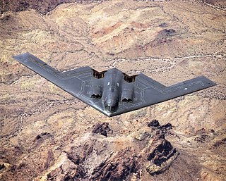
A flying wing is a tailless fixed-wing aircraft that has no definite fuselage, with its crew, payload, fuel, and equipment housed inside the main wing structure. A flying wing may have various small protuberances such as pods, nacelles, blisters, booms, or vertical stabilizers.
In aeronautics, the aspect ratio of a wing is the ratio of its span to its mean chord. It is equal to the square of the wingspan divided by the wing area. Thus, a long, narrow wing has a high aspect ratio, whereas a short, wide wing has a low aspect ratio.
In aerodynamics, the lift-to-drag ratio is the lift generated by an aerodynamic body such as an aerofoil or aircraft, divided by the aerodynamic drag caused by moving through air. It describes the aerodynamic efficiency under given flight conditions. The L/D ratio for any given body will vary according to these flight conditions.
Lift-induced drag, induced drag, vortex drag, or sometimes drag due to lift, in aerodynamics, is an aerodynamic drag force that occurs whenever a moving object redirects the airflow coming at it. This drag force occurs in airplanes due to wings or a lifting body redirecting air to cause lift and also in cars with airfoil wings that redirect air to cause a downforce. It is symbolized as , and the lift-induced drag coefficient as .
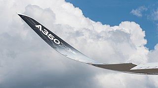
Wingtip devices are intended to improve the efficiency of fixed-wing aircraft by reducing drag. Although there are several types of wing tip devices which function in different manners, their intended effect is always to reduce an aircraft's drag. Wingtip devices can also improve aircraft handling characteristics and enhance safety for following aircraft. Such devices increase the effective aspect ratio of a wing without greatly increasing the wingspan. Extending the span would lower lift-induced drag, but would increase parasitic drag and would require boosting the strength and weight of the wing. At some point, there is no net benefit from further increased span. There may also be operational considerations that limit the allowable wingspan.
Ludwig Prandtl was a German fluid dynamicist, physicist and aerospace scientist. He was a pioneer in the development of rigorous systematic mathematical analyses which he used for underlying the science of aerodynamics, which have come to form the basis of the applied science of aeronautical engineering. In the 1920s, he developed the mathematical basis for the fundamental principles of subsonic aerodynamics in particular; and in general up to and including transonic velocities. His studies identified the boundary layer, thin-airfoils, and lifting-line theories. The Prandtl number was named after him.
In aeronautical and naval engineering, pusher configuration is the term used to describe a drivetrain of air- or watercraft with propulsion device(s) after the engine(s). This is in contrast to the more conventional tractor configuration, which places them in front.
Wingtip vortices are circular patterns of rotating air left behind a wing as it generates lift. The name is a misnomer because the cores of the vortices are slightly inboard of the wing tips. Wingtip vortices are sometimes named trailing or lift-induced vortices because they also occur at points other than at the wing tips. Indeed, vorticity is trailed at any point on the wing where the lift varies span-wise ; it eventually rolls up into large vortices near the wingtip, at the edge of flap devices, or at other abrupt changes in wing planform.
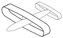
An elliptical wing is a wing planform whose leading and trailing edges each approximate two segments of an ellipse. It is not to be confused with annular wings, which may be elliptically shaped.
An adaptive compliant wing is a wing which is flexible enough for aspects of its shape to be changed in flight. Flexible wings have a number of benefits. Conventional flight control mechanisms operate using hinges, resulting in disruptions to the airflow, vortices, and in some cases, separation of the airflow. These effects contribute to the drag of the aircraft, resulting in less efficiency and higher fuel costs. Flexible aerofoils can manipulate aerodynamic forces with less disruptions to the flow, resulting in less aerodynamic drag and improved fuel economy.
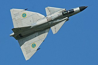
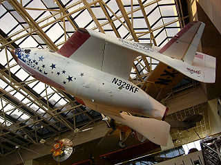
In aeronautics, a canard is a wing configuration in which a small forewing or foreplane is placed forward of the main wing of a fixed-wing aircraft or a weapon. The term "canard" may be used to describe the aircraft itself, the wing configuration, or the foreplane. Canard wings are also extensively used in guided missiles and smart bombs.
In aeronautics, a tailless aircraft is a fixed-wing aircraft with no other horizontal aerodynamic surface besides its main wing. It may still have a fuselage, vertical tail fin, and/or vertical rudder.
Washout is a characteristic of aircraft wing design which deliberately reduces the lift distribution across the span of an aircraft’s wing. The wing is designed so that the angle of incidence is greater at the wing roots and decreases across the span, becoming lowest at the wing tip. This is usually to ensure that at stall speed the wing root stalls before the wing tips, providing the aircraft with continued aileron control and some resistance to spinning. Washout may also be used to modify the spanwise lift distribution to reduce lift-induced drag.
The wing configuration or planform of a fixed-wing aircraft is its arrangement of lifting and related surfaces.
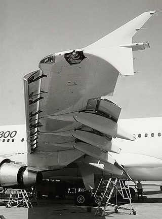
A slat is an aerodynamic surface on the leading edge of the wing of a fixed-wing aircraft. When retracted, the slat lies flush with the rest of the wing. A slat is deployed by sliding forward, opening a slot between the wing and the slat. Air from below the slat flows through the slot and replaces the boundary layer that has travelled at high speed around the leading edge of the slat, losing a significant amount of its kinetic energy due to skin friction drag. When deployed, slats allow the wings to operate at a higher angle of attack before stalling. With slats deployed an aircraft can fly at slower speeds, allowing it to take off and land in shorter distances. They are used during takeoff and landing and while performing low-speed maneuvers which may take the aircraft close to a stall. Slats are retracted in normal flight to minimize drag.
The fuel economy in aircraft is the measure of the transport energy efficiency of aircraft. Fuel efficiency is increased with better aerodynamics and by reducing weight, and with improved engine brake-specific fuel consumption and propulsive efficiency or thrust-specific fuel consumption. Endurance and range can be maximized with the optimum airspeed, and economy is better at optimum altitudes, usually higher. An airline efficiency depends on its fleet fuel burn, seating density, air cargo and passenger load factor, while operational procedures like maintenance and routing can save fuel.
An outboard tail is a type of aircraft tail or empennage which is split in two, with each half mounted on a short boom just behind and outboard of each wing tip. It comprises outboard horizontal stabilizers (OHS) and may or may not include additional boom-mounted vertical stabilizers (fins). OHS designs are sometimes described as a form of tailless aircraft.
The NASA X-57 Maxwell was an experimental aircraft developed by NASA, intended to demonstrate technology to reduce fuel use, emissions, and noise. The first flight of the X-57 was scheduled to take place in 2023, but the program was cancelled due to problems with the propulsion system.
The Preliminary Research Aerodynamic Design to Lower Drag, or Prandtl-D was a series of unmanned experimental glider-aircraft developed by NASA under aerodynamicist Albion Bowers. The acronym is a reference to early German Aerospace Engineer Ludwig Prandtl, whose theory of the bell-shaped lift distribution deeply influenced Bowers.
An annular lift fan aircraft is a conceptual vertical takeoff and landing (VTOL) aircraft that was first systematically and numerically investigated in 2015. This concept was proposed to offer a VTOL solution for both high hovering efficiency and high cruise speed, using a large annular lift fan instead of the relatively small conventional circular lift fans used in the Ryan XV-5 Vertifan and the F-35B Lightning II (JSF).