
Heating, ventilation, and air conditioning (HVAC) is the use of various technologies to control the temperature, humidity, and purity of the air in an enclosed space. Its goal is to provide thermal comfort and acceptable indoor air quality. HVAC system design is a subdiscipline of mechanical engineering, based on the principles of thermodynamics, fluid mechanics, and heat transfer. "Refrigeration" is sometimes added to the field's abbreviation as HVAC&R or HVACR, or "ventilation" is dropped, as in HACR.
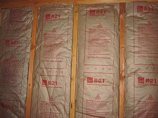
The R-value is a measure of how well a two-dimensional barrier, such as a layer of insulation, a window or a complete wall or ceiling, resists the conductive flow of heat, in the context of construction. R-value is the temperature difference per unit of heat flux needed to sustain one unit of heat flux between the warmer surface and colder surface of a barrier under steady-state conditions. The measure is therefore equally relevant for lowering energy bills for heating in the winter, for cooling in the summer, and for general comfort.

Heating degree day (HDD) is a measurement designed to quantify the demand for energy needed to heat a building. HDD is derived from measurements of outside air temperature. The estimated average heating energy requirements for a given building at a specific location are considered to be directly proportional to the number of HDD at that location.

Underfloor heating and cooling is a form of central heating and cooling that achieves indoor climate control for thermal comfort using hydronic or electrical heating elements embedded in a floor. Heating is achieved by conduction, radiation and convection. Use of underfloor heating dates back to the Neoglacial and Neolithic periods.

A reaction calorimeter is a calorimeter that measures the amount of energy released or absorbed by a chemical reaction. It does this by measuring the total change in temperature of an exact amount of water in a vessel.

A ground source heat pump is a heating/cooling system for buildings that use a type of heat pump to transfer heat to or from the ground, taking advantage of the relative constancy of temperatures of the earth through the seasons. Ground-source heat pumps (GSHPs)—or geothermal heat pumps (GHP), as they are commonly termed in North America—are among the most energy-efficient technologies for providing HVAC and water heating, using less energy than can be achieved by use of resistive electric heaters.
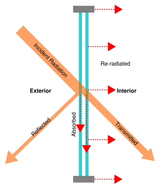
Solar gain is the increase in thermal energy of a space, object or structure as it absorbs incident solar radiation. The amount of solar gain a space experiences is a function of the total incident solar irradiance and of the ability of any intervening material to transmit or resist the radiation.

Thermal comfort is the condition of mind that expresses subjective satisfaction with the thermal environment. The human body can be viewed as a heat engine where food is the input energy. The human body will release excess heat into the environment, so the body can continue to operate. The heat transfer is proportional to temperature difference. In cold environments, the body loses more heat to the environment and in hot environments the body does not release enough heat. Both the hot and cold scenarios lead to discomfort. Maintaining this standard of thermal comfort for occupants of buildings or other enclosures is one of the important goals of HVAC design engineers.
Sol-air temperature (Tsol-air) is a variable used to calculate cooling load of a building and determine the total heat gain through exterior surfaces. It is an improvement over:
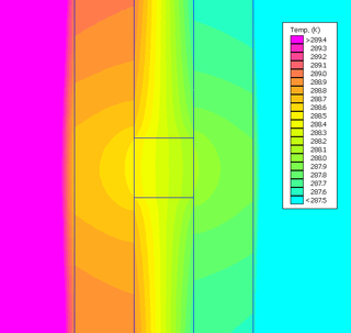
A thermal bridge, also called a cold bridge, heat bridge, or thermal bypass, is an area or component of an object which has higher thermal conductivity than the surrounding materials, creating a path of least resistance for heat transfer. Thermal bridges result in an overall reduction in thermal resistance of the object. The term is frequently discussed in the context of a building's thermal envelope where thermal bridges result in heat transfer into or out of conditioned space.
Free cooling is an economical method of using low external air temperatures to assist in chilling water, which can then be used for industrial processes, or air conditioning systems. The chilled water can either be used immediately or be stored for the short- or long-term. When outdoor temperatures are lower relative to indoor temperatures, this system utilizes the cool outdoor air as a free cooling source. In this manner, the system replaces the chiller in traditional air conditioning systems while achieving the same cooling result. Such systems can be made for single buildings or district cooling networks.
HVAC is a major sub discipline of mechanical engineering. The goal of HVAC design is to balance indoor environmental comfort with other factors such as installation cost, ease of maintenance, and energy efficiency. The discipline of HVAC includes a large number of specialized terms and acronyms, many of which are summarized in this glossary.
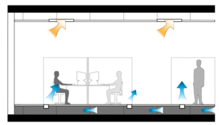
Underfloor air distribution (UFAD) is an air distribution strategy for providing ventilation and space conditioning in buildings as part of the design of a HVAC system. UFAD systems use an underfloor supply plenum located between the structural concrete slab and a raised floor system to supply conditioned air to supply outlets, located at or near floor level within the occupied space. Air returns from the room at ceiling level or the maximum allowable height above the occupied zone.
ANSI/ASHRAE/IES Standard 90.1: Energy Standard for Buildings Except Low-Rise Residential Buildings is an American National Standards Institute (ANSI) standard published by ASHRAE and jointly sponsored by the Illuminating Engineering Society (IES) that provides minimum requirements for energy efficient designs for buildings except for low-rise residential buildings. The original standard, ASHRAE 90, was published in 1975. There have been multiple editions to it since. In 1999 the ASHRAE Board of Directors voted to place the standard on continuous maintenance, based on rapid changes in energy technology and energy prices. This allows it to be updated multiple times in a year. The standard was renamed ASHRAE 90.1 in 2001. It has since been updated in 2004, 2007, 2010, 2013, 2016, and 2019 to reflect newer and more efficient technologies.
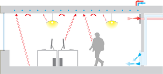
Radiant heating and cooling is a category of HVAC technologies that exchange heat by both convection and radiation with the environments they are designed to heat or cool. There are many subcategories of radiant heating and cooling, including: "radiant ceiling panels", "embedded surface systems", "thermally active building systems", and infrared heaters. According to some definitions, a technology is only included in this category if radiation comprises more than 50% of its heat exchange with the environment; therefore technologies such as radiators and chilled beams are usually not considered radiant heating or cooling. Within this category, it is practical to distinguish between high temperature radiant heating, and radiant heating or cooling with more moderate source temperatures. This article mainly addresses radiant heating and cooling with moderate source temperatures, used to heat or cool indoor environments. Moderate temperature radiant heating and cooling is usually composed of relatively large surfaces that are internally heated or cooled using hydronic or electrical sources. For high temperature indoor or outdoor radiant heating, see: Infrared heater. For snow melt applications see: Snowmelt system.
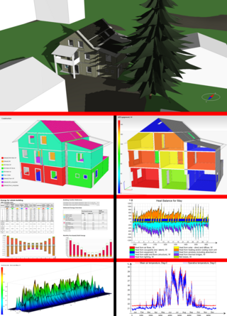
Building performance simulation (BPS) is the replication of aspects of building performance using a computer-based, mathematical model created on the basis of fundamental physical principles and sound engineering practice. The objective of building performance simulation is the quantification of aspects of building performance which are relevant to the design, construction, operation and control of buildings. Building performance simulation has various sub-domains; most prominent are thermal simulation, lighting simulation, acoustical simulation and air flow simulation. Most building performance simulation is based on the use of bespoke simulation software. Building performance simulation itself is a field within the wider realm of scientific computing.
The Glossary of Geothermal Heating and Cooling provides definitions of many terms used within the Geothermal heat pump industry. The terms in this glossary may be used by industry professionals, for education materials, and by the general public.
ANSI/ASHRAE Standard 55: Thermal Environmental Conditions for Human Occupancy is an American National Standard published by ASHRAE that establishes the ranges of indoor environmental conditions to achieve acceptable thermal comfort for occupants of buildings. It was first published in 1966, and since 2004 has been updated every three to six years. The most recent version of the standard was published in 2023.

The building balance point temperature is the outdoor air temperature when the heat gains of the building are equal to the heat losses. Internal heat sources due to electric lighting, mechanical equipment, body heat, and solar radiation may offset the need for additional heating although the outdoor temperature may be below the thermostat set-point temperature.
Cooling load is the rate at which sensible and latent heat must be removed from the space to maintain a constant space dry-bulb air temperature and humidity. Sensible heat into the space causes its air temperature to rise while latent heat is associated with the rise of the moisture content in the space. The building design, internal equipment, occupants, and outdoor weather conditions may affect the cooling load in a building using different heat transfer mechanisms. The SI units are watts.