
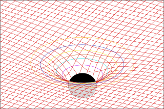
The stress–energy tensor, sometimes called the stress–energy–momentum tensor or the energy–momentum tensor, is a tensor physical quantity that describes the density and flux of energy and momentum in spacetime, generalizing the stress tensor of Newtonian physics. It is an attribute of matter, radiation, and non-gravitational force fields. This density and flux of energy and momentum are the sources of the gravitational field in the Einstein field equations of general relativity, just as mass density is the source of such a field in Newtonian gravity.
In mathematics, a Gaussian function, often simply referred to as a Gaussian, is a function of the base form and with parametric extension for arbitrary real constants a, b and non-zero c. It is named after the mathematician Carl Friedrich Gauss. The graph of a Gaussian is a characteristic symmetric "bell curve" shape. The parameter a is the height of the curve's peak, b is the position of the center of the peak, and c controls the width of the "bell".
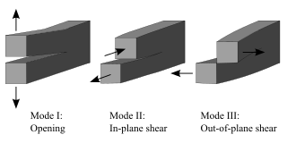
Fracture mechanics is the field of mechanics concerned with the study of the propagation of cracks in materials. It uses methods of analytical solid mechanics to calculate the driving force on a crack and those of experimental solid mechanics to characterize the material's resistance to fracture.
The Einstein–Hilbert action in general relativity is the action that yields the Einstein field equations through the stationary-action principle. With the (− + + +) metric signature, the gravitational part of the action is given as
In physics, the Polyakov action is an action of the two-dimensional conformal field theory describing the worldsheet of a string in string theory. It was introduced by Stanley Deser and Bruno Zumino and independently by L. Brink, P. Di Vecchia and P. S. Howe in 1976, and has become associated with Alexander Polyakov after he made use of it in quantizing the string in 1981. The action reads:
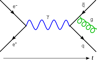
In quantum field theory, the Lehmann–Symanzik–Zimmermann (LSZ) reduction formula is a method to calculate S-matrix elements from the time-ordered correlation functions of a quantum field theory. It is a step of the path that starts from the Lagrangian of some quantum field theory and leads to prediction of measurable quantities. It is named after the three German physicists Harry Lehmann, Kurt Symanzik and Wolfhart Zimmermann.
In general relativity, the Gibbons–Hawking–York boundary term is a term that needs to be added to the Einstein–Hilbert action when the underlying spacetime manifold has a boundary.

In relativistic physics, the electromagnetic stress–energy tensor is the contribution to the stress–energy tensor due to the electromagnetic field. The stress–energy tensor describes the flow of energy and momentum in spacetime. The electromagnetic stress–energy tensor contains the negative of the classical Maxwell stress tensor that governs the electromagnetic interactions.
The covariant formulation of classical electromagnetism refers to ways of writing the laws of classical electromagnetism in a form that is manifestly invariant under Lorentz transformations, in the formalism of special relativity using rectilinear inertial coordinate systems. These expressions both make it simple to prove that the laws of classical electromagnetism take the same form in any inertial coordinate system, and also provide a way to translate the fields and forces from one frame to another. However, this is not as general as Maxwell's equations in curved spacetime or non-rectilinear coordinate systems.
In physics, Maxwell's equations in curved spacetime govern the dynamics of the electromagnetic field in curved spacetime or where one uses an arbitrary coordinate system. These equations can be viewed as a generalization of the vacuum Maxwell's equations which are normally formulated in the local coordinates of flat spacetime. But because general relativity dictates that the presence of electromagnetic fields induce curvature in spacetime, Maxwell's equations in flat spacetime should be viewed as a convenient approximation.
The Newman–Penrose (NP) formalism is a set of notation developed by Ezra T. Newman and Roger Penrose for general relativity (GR). Their notation is an effort to treat general relativity in terms of spinor notation, which introduces complex forms of the usual variables used in GR. The NP formalism is itself a special case of the tetrad formalism, where the tensors of the theory are projected onto a complete vector basis at each point in spacetime. Usually this vector basis is chosen to reflect some symmetry of the spacetime, leading to simplified expressions for physical observables. In the case of the NP formalism, the vector basis chosen is a null tetrad: a set of four null vectors—two real, and a complex-conjugate pair. The two real members often asymptotically point radially inward and radially outward, and the formalism is well adapted to treatment of the propagation of radiation in curved spacetime. The Weyl scalars, derived from the Weyl tensor, are often used. In particular, it can be shown that one of these scalars— in the appropriate frame—encodes the outgoing gravitational radiation of an asymptotically flat system.
In statistics, the multivariate t-distribution is a multivariate probability distribution. It is a generalization to random vectors of the Student's t-distribution, which is a distribution applicable to univariate random variables. While the case of a random matrix could be treated within this structure, the matrix t-distribution is distinct and makes particular use of the matrix structure.

The lateral earth pressure is the pressure that soil exerts in the horizontal direction. It is important because it affects the consolidation behavior and strength of the soil and because it is considered in the design of geotechnical engineering structures such as retaining walls, basements, tunnels, deep foundations and braced excavations.

Contact mechanics is the study of the deformation of solids that touch each other at one or more points. A central distinction in contact mechanics is between stresses acting perpendicular to the contacting bodies' surfaces and frictional stresses acting tangentially between the surfaces. Normal contact mechanics or frictionless contact mechanics focuses on normal stresses caused by applied normal forces and by the adhesion present on surfaces in close contact, even if they are clean and dry. Frictional contact mechanics emphasizes the effect of friction forces.

In mathematical finance, the Black–Scholes equation, also called the Black–Scholes–Merton equation, is a partial differential equation (PDE) governing the price evolution of derivatives under the Black–Scholes model. Broadly speaking, the term may refer to a similar PDE that can be derived for a variety of options, or more generally, derivatives.
In physics, particularly special relativity, light-cone coordinates, introduced by Paul Dirac and also known as Dirac coordinates, are a special coordinate system where two coordinate axes combine both space and time, while all the others are spatial.

The vibration of plates is a special case of the more general problem of mechanical vibrations. The equations governing the motion of plates are simpler than those for general three-dimensional objects because one of the dimensions of a plate is much smaller than the other two. This permits a two-dimensional plate theory to give an excellent approximation to the actual three-dimensional motion of a plate-like object.

Crack tip opening displacement (CTOD) or is the distance between the opposite faces of a crack tip at the 90° intercept position. The position behind the crack tip at which the distance is measured is arbitrary but commonly used is the point where two 45° lines, starting at the crack tip, intersect the crack faces. The parameter is used in fracture mechanics to characterize the loading on a crack and can be related to other crack tip loading parameters such as the stress intensity factor and the elastic-plastic J-integral.
In string theory, the Ramond–Neveu–Schwarz (RNS) formalism is an approach to formulating superstrings in which the worldsheet has explicit superconformal invariance but spacetime supersymmetry is hidden, in contrast to the Green–Schwarz formalism where the latter is explicit. It was originally developed by Pierre Ramond, André Neveu and John Schwarz in the RNS model in 1971, which gives rise to type II string theories and can also give type I string theory. Heterotic string theories can also be acquired through this formalism by using a different worldsheet action. There are various ways to quantize the string within this framework including light-cone quantization, old canonical quantization, and BRST quantization. A consistent string theory is only acquired if the spectrum of states is restricted through a procedure known as a GSO projection, with this projection being automatically present in the Green–Schwarz formalism.
Fastran is a computer program for calculating the rate of fatigue crack growth by combining crack growth equations and a simulation of the plasticity at the crack tip.


