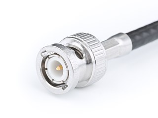
The BNC connector is a miniature quick connect/disconnect radio frequency connector used for coaxial cable. It is designed to maintain the same characteristic impedance of the cable, with 50 ohm and 75 ohm types being made. It is usually applied for video and radio frequency connections up to about 2 GHz and up to 500 volts. The connector has a twist to lock design with two lugs in the female portion of the connector engaging a slot in the shell of the male portion. The type was introduced on military radio equipment in the 1940s and has since become widely applied in radio systems, and is a common type of video connector. Similar radio-frequency connectors differ in dimensions and attachment features, and may allow for higher voltages, higher frequencies, or three-wire connections.

Components of an electrical circuit are electrically connected if an electric current can run between them through an electrical conductor. An electrical connector is an electromechanical device used to create an electrical connection between parts of an electrical circuit, or between different electrical circuits, thereby joining them into a larger circuit. Most electrical connectors have a gender – i.e. the male component, called a plug, connects to the female component, or socket. The connection may be removable, require a tool for assembly and removal, or serve as a permanent electrical joint between two points. An adapter can be used to join dissimilar connectors.

A ferrule is any of a number of types of objects, generally used for fastening, joining, sealing, or reinforcement. They are often narrow circular rings made from metal, or less commonly, plastic. Ferrules are also often referred to as eyelets or grommets within the manufacturing industry.

The D-subminiature or D-sub is a common type of electrical connector. They are named for their characteristic D-shaped metal shield. When they were introduced, D-subs were among the smallest connectors used on computer systems.

Pliers are a hand tool used to hold objects firmly, possibly developed from tongs used to handle hot metal in Bronze Age Europe. They are also useful for bending and physically compressing a wide range of materials. Generally, pliers consist of a pair of metal first-class levers joined at a fulcrum positioned closer to one end of the levers, creating short jaws on one side of the fulcrum, and longer handles on the other side. This arrangement creates a mechanical advantage, allowing the force of the grip strength to be amplified and focused on an object with precision. The jaws can also be used to manipulate objects too small or unwieldy to be manipulated with the fingers.

A banana connector is a single-wire electrical connector used for joining wires to equipment. The term 4 mm connector is also used, especially in Europe, although not all banana connectors will mate with 4 mm parts, and 2 mm banana connectors exist. Various styles of banana plug contacts exist, all based on the concept of spring metal applying outward force into the unsprung cylindrical jack to produce a snug fit with good electrical conductivity. Common types include: a solid pin split lengthwise and splayed slightly, a tip of four leaf springs, a cylinder with a single leaf spring on one side, a bundle of stiff wire, a central pin surrounded by a multiple-slit cylinder with a central bulge, or simple sheet spring metal rolled into a nearly complete cylinder. The plugs are frequently used to terminate patch cords for electronic test equipment such as laboratory power supply units, while sheathed banana plugs are common on multimeter probe leads.
A Digital Signal 3 (DS3) is a digital signal level 3 T-carrier. It may also be referred to as a T3 line.

A terminal is the point at which a conductor from a component, device or network comes to an end. Terminal may also refer to an electrical connector at this endpoint, acting as the reusable interface to a conductor and creating a point where external circuits can be connected. A terminal may simply be the end of a wire or it may be fitted with a connector or fastener.

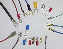
Crimping is a method of joining two or more pieces of metal or other ductile material by deforming one or both of them to hold the other. The bend or deformity is called the crimp. Crimping tools are used to create crimps.

Twist-on wire connectors are a type of electrical connector used to fasten two or more low-voltage electrical conductors. They are widely used in North America and several European countries in residential, commercial and industrial building power wiring, but have been banned in some other jurisdictions.
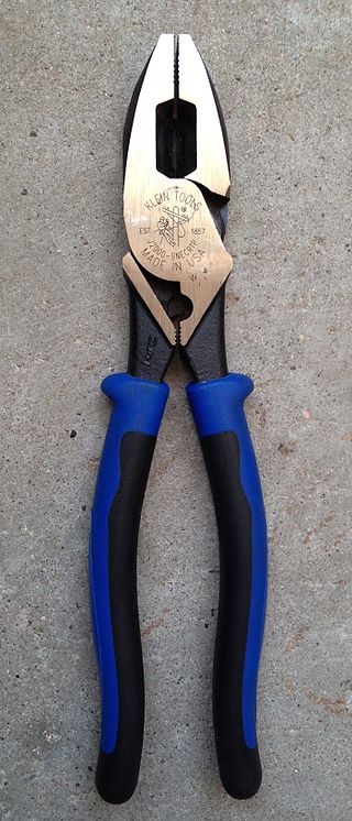
Lineman's pliers, Kleins, linesman pliers, side cutting linesman pliers and combination pliers are a type of pliers used by lineworkers, electricians, and other tradespeople primarily for gripping, twisting, bending and cutting wire, cable, and small metalwork components. They owe their effectiveness to their plier design, which multiplies force through leverage.

A modular connector is a type of electrical connector for cords and cables of electronic devices and appliances, such as in computer networking, telecommunication equipment, and audio headsets.

The Western Union splice or Lineman splice is a method of joining electrical cable, developed in the nineteenth century during the introduction of the telegraph and named for the Western Union telegraph company. This method can be used where the cable may be subject to loading stress. The wrapping pattern design causes the join to tighten as the conductors pull against each other.

A keystone module is a standardized snap-in package for mounting a variety of low-voltage electrical jacks or optical connectors into a keystone wall plate, face plate, surface-mount box, or a patch panel.

A screw terminal is a type of electrical connection where a wire is held by the tightening of a screw.
F-Crimp is a type of solderless electrical crimp connection. It is not related to the F connector common in RF equipment.
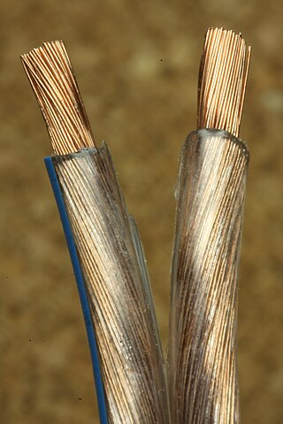
Copper has been used in electrical wiring since the invention of the electromagnet and the telegraph in the 1820s. The invention of the telephone in 1876 created further demand for copper wire as an electrical conductor.

A swaged sleeve is a connector that gets crimped using a hand tool and die (swaged). This type of compressed sleeve is commonly used to make mechanical or conductive connections. These sleeves join or terminate wire rope, aircraft cable, synthetic cable, fibrous rope, or electrical conductor cables.

FASTON terminals or faston terminals are connectors that are widely used in electronic and electrical equipment. These terminals are manufactured by many companies, commonly using the terms "quick disconnect", "quick connect", "tab" terminals, or blade connectors; without qualifiers, the first two could be mistaken for plumbing connections.
In telecommunications, a line splice is a method of connecting electrical cables or optical fibers.

 Klein modular connector crimpers
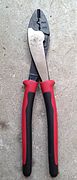 Klein Journeyman crimpers
 Crimping pliers, which can also strip and cut wire
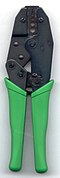 Crimping tool for F connectors and other hexagonal connectors


