This article has multiple issues. Please help improve it or discuss these issues on the talk page . (Learn how and when to remove these messages)
|
The Crossbar latch is a technology published by Phillip Kuekes of HP Labs in 2001 and granted a US patent in 2003, [1] with the goal of eventually replacing transistors in various applications. [2] This would enable the creation of integrated circuits composed solely of memristors, which, according to the patent, might be easier and less expensive to create. In 2005, Phillip Kuekes stated that the crossbar latch "could someday replace transistors in computers, just as transistors replaced vacuum tubes and vacuum tubes replaced electromagnetic relays before them." [3]
The crossbar latch was introduced by HP Labs scientists in the Journal of Applied Physics, which provides a basis for constructing logic gates using memristors. The crossbar latch consists of a signal line crossed by two control lines. Depending on the voltages sent down the various lines, it can simulate the action of the three major logic gates: AND, OR and NOT.
The abstract of the patent is as follows:
"A molecular crossbar latch is provided, comprising two control wires and a signal wire that crosses the two control wires at a non-zero angle to thereby form a junction with each control wire. Each junction forms a switch and the junction has a functional dimension in nanometers. The signal wire selectively has at least two different voltage states, ranging from a 0 state to a 1 state, wherein there is an asymmetry with respect to the direction of current flow from the signal wire through one junction compared to another junction such that current flowing through one junction into (out of) the signal wire can open (close) while current flowing through the other junction out of (into) the signal wire can close (open) the switch, and wherein there is a voltage threshold for switching between an open switch and a closed switch. Further, methods are provided for latching logic values onto nanowires in a logic array, for inverting a logic value, and for restoring a voltage value of a signal in a nano-scale wire. Invented by Phillip J Kuekes."
— U.S. patent 6,586,965 [4]
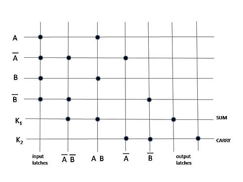
Greg Snider of Hewlett-Packard created this application, which uses crossbar latches to imitate the functionality of a half adder, which is the foundation of modern computing systems. [5] A crossbar tile is created in this application from a layer of horizontal row wires and a layer of vertical column wires, with memristor or similar materials sandwiched between the horizontal and vertical wire layers. Each crossbar tile intersection or junction can be configured to be in a high-resistance state with little or no current flowing between the horizontal and vertical wires, or in a low-resistance state with current flowing. Fig. 1 illustrates the configuration of a half-adder using a crossbar tile, as taught by Snider, with the nodes identifying junctions of the crossbar tile configured as low-resistance states. By setting different logic inputs A, NOT A, B, and NOT B to different row wires this configuration produces the sum and carry outputs typical for a half-adder. Connections between multiple half-adders may then be used to form full adders in accordance with conventional arithmetic architectures.
Crossbar latches have been suggested as components of neuromorphic computing systems. One implementation of this is in the form of a neural network formed from nanowires as discussed in a patent by Greg Snider of Hewlett-Packard.[ citation needed ]
A logic gate is a device that performs a Boolean function, a logical operation performed on one or more binary inputs that produces a single binary output. Depending on the context, the term may refer to an ideal logic gate, one that has, for instance, zero rise time and unlimited fan-out, or it may refer to a non-ideal physical device.
A transistor is a semiconductor device used to amplify or switch electrical signals and power. It is one of the basic building blocks of modern electronics. It is composed of semiconductor material, usually with at least three terminals for connection to an electronic circuit. A voltage or current applied to one pair of the transistor's terminals controls the current through another pair of terminals. Because the controlled (output) power can be higher than the controlling (input) power, a transistor can amplify a signal. Some transistors are packaged individually, but many more in miniature form are found embedded in integrated circuits. Because transistors are the key active components in practically all modern electronics, many people consider them one of the 20th century's greatest inventions.
Digital electronics is a field of electronics involving the study of digital signals and the engineering of devices that use or produce them. This is in contrast to analog electronics which work primarily with analog signals. Despite the name, digital electronics designs includes important analog design considerations.
In electronics, the metal–oxide–semiconductor field-effect transistor is a type of field-effect transistor (FET), most commonly fabricated by the controlled oxidation of silicon. It has an insulated gate, the voltage of which determines the conductivity of the device. This ability to change conductivity with the amount of applied voltage can be used for amplifying or switching electronic signals. The term metal–insulator–semiconductor field-effect transistor (MISFET) is almost synonymous with MOSFET. Another near-synonym is insulated-gate field-effect transistor (IGFET).
In electronics and telecommunications, a crossbar switch is a collection of switches arranged in a matrix configuration. A crossbar switch has multiple input and output lines that form a crossed pattern of interconnecting lines between which a connection may be established by closing a switch located at each intersection, the elements of the matrix. Originally, a crossbar switch consisted literally of crossing metal bars that provided the input and output paths. Later implementations achieved the same switching topology in solid-state electronics. The crossbar switch is one of the principal telephone exchange architectures, together with a rotary switch, memory switch, and a crossover switch.
An insulated-gate bipolar transistor (IGBT) is a three-terminal power semiconductor device primarily forming an electronic switch. It was developed to combine high efficiency with fast switching. It consists of four alternating layers (NPNP) that are controlled by a metal–oxide–semiconductor (MOS) gate structure.
A TRIAC is a three-terminal electronic component that conducts current in either direction when triggered. The term TRIAC is a genericised trademark.
An electronic component is any basic discrete electronic device or physical entity part of an electronic system used to affect electrons or their associated fields. Electronic components are mostly industrial products, available in a singular form and are not to be confused with electrical elements, which are conceptual abstractions representing idealized electronic components and elements. A datasheet for an electronic component is a technical document that provides detailed information about the component's specifications, characteristics, and performance. Discrete circuits are made of individual electronic components that only perform one function each as packaged, which are known as discrete components, although strictly the term discrete component refers to such a component with semiconductor material such as individual transistors.
A power MOSFET is a specific type of metal–oxide–semiconductor field-effect transistor (MOSFET) designed to handle significant power levels. Compared to the other power semiconductor devices, such as an insulated-gate bipolar transistor (IGBT) or a thyristor, its main advantages are high switching speed and good efficiency at low voltages. It shares with the IGBT an isolated gate that makes it easy to drive. They can be subject to low gain, sometimes to a degree that the gate voltage needs to be higher than the voltage under control.
An electronic symbol is a pictogram used to represent various electrical and electronic devices or functions, such as wires, batteries, resistors, and transistors, in a schematic diagram of an electrical or electronic circuit. These symbols are largely standardized internationally today, but may vary from country to country, or engineering discipline, based on traditional conventions.
Integrated injection logic (IIL, I2L, or I2L) is a class of digital circuits built with multiple collector bipolar junction transistors (BJT). When introduced it had speed comparable to TTL yet was almost as low power as CMOS, making it ideal for use in VLSI (and larger) integrated circuits. The gates can be made smaller with this logic family than with CMOS because complementary transistors are not needed. Although the logic voltage levels are very close (High: 0.7V, Low: 0.2V), I2L has high noise immunity because it operates by current instead of voltage. I2L was developed in 1971 by Siegfried K. Wiedmann and Horst H. Berger who originally called it merged-transistor logic (MTL). A disadvantage of this logic family is that the gates draw power when not switching unlike with CMOS.
Nanoelectronics refers to the use of nanotechnology in electronic components. The term covers a diverse set of devices and materials, with the common characteristic that they are so small that inter-atomic interactions and quantum mechanical properties need to be studied extensively. Some of these candidates include: hybrid molecular/semiconductor electronics, one-dimensional nanotubes/nanowires or advanced molecular electronics.
An electronic circuit is composed of individual electronic components, such as resistors, transistors, capacitors, inductors and diodes, connected by conductive wires or traces through which electric current can flow. It is a type of electrical circuit. For a circuit to be referred to as electronic, rather than electrical, generally at least one active component must be present. The combination of components and wires allows various simple and complex operations to be performed: signals can be amplified, computations can be performed, and data can be moved from one place to another.
Resistive random-access memory is a type of non-volatile (NV) random-access (RAM) computer memory that works by changing the resistance across a dielectric solid-state material, often referred to as a memristor. One major advantage of ReRAM over other NVRAM technologies is the ability to scale below 10 nm.
Nanocircuits are electrical circuits operating on the nanometer scale where quantum mechanical effects become important. One nanometer is equal to 10−9 meters or a row of 10 hydrogen atoms. With such progressively smaller circuits, more can be fitted on a computer chip. This allows faster and more complex functions using less power. Nanocircuits are composed of three different fundamental components. These are transistors, interconnections, and architecture, all fabricated on the nanometer scale.
A memristor is a non-linear two-terminal electrical component relating electric charge and magnetic flux linkage. It was described and named in 1971 by Leon Chua, completing a theoretical quartet of fundamental electrical components which also comprises the resistor, capacitor and inductor.
A physical neural network is a type of artificial neural network in which an electrically adjustable material is used to emulate the function of a neural synapse or a higher-order (dendritic) neuron model. "Physical" neural network is used to emphasize the reliance on physical hardware used to emulate neurons as opposed to software-based approaches. More generally the term is applicable to other artificial neural networks in which a memristor or other electrically adjustable resistance material is used to emulate a neural synapse.
In electronics, pass transistor logic (PTL) describes several logic families used in the design of integrated circuits. It reduces the count of transistors used to make different logic gates, by eliminating redundant transistors. Transistors are used as switches to pass logic levels between nodes of a circuit, instead of as switches connected directly to supply voltages. This reduces the number of active devices, but has the disadvantage that the difference of the voltage between high and low logic levels decreases at each stage. Each transistor in series is less saturated at its output than at its input. If several devices are chained in series in a logic path, a conventionally constructed gate may be required to restore the signal voltage to the full value. By contrast, conventional CMOS logic switches transistors so the output connects to one of the power supply rails, so logic voltage levels in a sequential chain do not decrease. Simulation of circuits may be required to ensure adequate performance.
The following outline is provided as an overview of and topical guide to electronics:
The Caravelli-Traversa-Di Ventra equation (CTDV) is a closed-form equation to the evolution of networks of memristors. It was derived by Francesco Caravelli, Fabio L. Traversa and Massimiliano Di Ventra to study the exact evolution of complex circuits made of resistances with memory (memristors).