Diffraction of a scalar wave passing through a 1-wavelength-wide slitDiffraction of a scalar wave passing through a 4-wavelength-wide slit
General diffraction
Because diffraction is the result of addition of all waves (of given wavelength) along all unobstructed paths, the usual procedure is to consider the contribution of an infinitesimally small neighborhood around a certain path (this contribution is usually called a wavelet) and then integrate over all paths (= add all wavelets) from the source to the detector (or given point on a screen).
Thus in order to determine the pattern produced by diffraction, the phase and the amplitude of each of the wavelets is calculated. That is, at each point in space we must determine the distance to each of the simple sources on the incoming wavefront. If the distance to each of the simple sources differs by an integer number of wavelengths, all the wavelets will be in phase, resulting in constructive interference. If the distance to each source is an integer plus one half of a wavelength, there will be complete destructive interference. Usually, it is sufficient to determine these minima and maxima to explain the observed diffraction effects.
The simplest descriptions of diffraction are those in which the situation can be reduced to a two-dimensional problem. For water waves, this is already the case, as water waves propagate only on the surface of the water. For light, we can often neglect one dimension if the diffracting object extends in that direction over a distance far greater than the wavelength. In the case of light shining through small circular holes we will have to take into account the full three-dimensional nature of the problem.
Several qualitative observations can be made of diffraction in general:
The angular spacing of the features in the diffraction pattern is inversely proportional to the dimensions of the object causing the diffraction. In other words: the smaller the diffracting object, the wider the resulting diffraction pattern, and vice versa. (More precisely, this is true of the sines of the angles.)
The diffraction angles are invariant under scaling; that is, they depend only on the ratio of the wavelength to the size of the diffracting object.
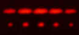
When the diffracting object has a periodic structure, for example in a diffraction grating, the features generally become sharper. The fourth figure, for example, shows a comparison of a double-slit pattern with a pattern formed by five slits, both sets of slits having the same spacing between the center of one slit and the next.
Approximations
The problem of calculating what a diffracted wave looks like, is the problem of determining the phase of each of the simple sources on the incoming wave front. It is mathematically easier to consider the case of far-field or Fraunhofer diffraction, where the point of observation is far from that of the diffracting obstruction, and as a result, involves less complex mathematics than the more general case of near-field or Fresnel diffraction. To make this statement more quantitative, consider a diffracting object at the origin that has a size . For definiteness let us say we are diffracting light and we are interested in what the intensity looks like on a screen a distance away from the object. At some point on the screen the path length to one side of the object is given by the Pythagorean theorem
If we now consider the situation where , the path length becomes
This is the Fresnel approximation. To further simplify things: If the diffracting object is much smaller than the distance , the last term will contribute much less than a wavelength to the path length, and will then not change the phase appreciably. That is . The result is the Fraunhofer approximation, which is only valid very far away from the object
Depending on the size of the diffraction object, the distance to the object and the wavelength of the wave, the Fresnel approximation, the Fraunhofer approximation or neither approximation may be valid. As the distance between the measured point of diffraction and the obstruction point increases, the diffraction patterns or results predicted converge towards those of Fraunhofer diffraction, which is more often observed in nature due to the extremely small wavelength of visible light.
Diffraction from an array of narrow slits
A simple quantitative description
Diagram of a two slit diffraction problem, showing the angle to the first minimum, where a path length difference of a half wavelength causes destructive interference.
Multiple-slit arrangements can be mathematically considered as multiple simple wave sources, if the slits are narrow enough. For light, a slit is an opening that is infinitely extended in one dimension, and this has the effect of reducing a wave problem in 3D-space to a simpler problem in 2D-space. The simplest case is that of two narrow slits, spaced a distance apart. To determine the maxima and minima in the amplitude we must determine the path difference to the first slit and to the second one. In the Fraunhofer approximation, with the observer far away from the slits, the difference in path length to the two slits can be seen from the image to be
Maxima in the intensity occur if this path length difference is an integer number of wavelengths.
where
is an integer that labels the order of each maximum,
is the wavelength,
is the distance between the slits
and is the angle at which constructive interference occurs.
The corresponding minima are at path differences of an integer number plus one half of the wavelength:
.
For an array of slits, positions of the minima and maxima are not changed, the fringes visible on a screen however do become sharper, as can be seen in the image.
2-slit and 5-slit diffraction of red laser light
Mathematical description
To calculate this intensity pattern, one needs to introduce some more sophisticated methods. The mathematical representation of a radial wave is given by
where , is the wavelength, is frequency of the wave and is the phase of the wave at the slits at time t=0. The wave at a screen some distance away from the plane of the slits is given by the sum of the waves emanating from each of the slits. To make this problem a little easier, we introduce the complex wave , the real part of which is equal to
The absolute value of this function gives the wave amplitude, and the complex phase of the function corresponds to the phase of the wave. is referred to as the complex amplitude. With slits, the total wave at point on the screen is
.
Since we are for the moment only interested in the amplitude and relative phase, we can ignore any overall phase factors that are not dependent on or . We approximate . In the Fraunhofer limit we can neglect terms of order: in the exponential, and any terms involving or in the denominator. The sum becomes
The sum has the form of a geometric sum and can be evaluated to give
The intensity is given by the absolute value of the complex amplitude squared
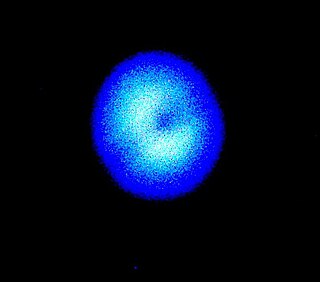
Numerical approximation of diffraction pattern from a slit of width equal to wavelength of an incident plane wave in 3D blue visualizationNumerical approximation of diffraction pattern from a slit of width four wavelengths with an incident plane wave. The main central beam, nulls, and phase reversals are apparent.Graph and image of single-slit diffraction
As an example, an exact equation can now be derived for the intensity of the diffraction pattern as a function of angle in the case of single-slit diffraction.
A mathematical representation of Huygens' principle can be used to start an equation.
Consider a monochromatic complex plane wave of wavelength λ incident on a slit of width a.
If the slit lies in the x′-y′ plane, with its center at the origin, then it can be assumed that diffraction generates a complex wave ψ, traveling radially in the r direction away from the slit, and this is given by:
Let (x′,y′,0) be a point inside the slit over which it is being integrated. If (x,0,z) is the location at which the intensity of the diffraction pattern is being computed, the slit extends from to , and from to .
The distance r from the slot is:
Assuming Fraunhofer diffraction will result in the conclusion . In other words, the distance to the target is much larger than the diffraction width on the target. By the binomial expansion rule, ignoring terms quadratic and higher, the quantity on the right can be estimated to be:
It can be seen that 1/r in front of the equation is non-oscillatory, i.e. its contribution to the magnitude of the intensity is small compared to our exponential factors. Therefore, we will lose little accuracy by approximating it as 1/z.
To make things cleaner, a placeholder 'C' is used to denote constants in the equation. It is important to keep in mind that C can contain imaginary numbers, thus the wave function will be complex. However, at the end, the ψ will be bracketed, which will eliminate any imaginary components.
Now, in Fraunhofer diffraction, is small, so (note that participates in this exponential and it is being integrated).
In contrast the term can be eliminated from the equation, since when bracketed it gives 1.
(For the same reason we have also eliminated the term )
Taking results in:
It can be noted through Euler's formula and its derivatives that and .
where the (unnormalized) sinc function is defined by .
Now, substituting in , the intensity (squared amplitude) of the diffracted waves at an angle θ is given by:
Quantitative analysis of N-slit diffraction
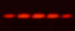
Double-slit diffraction of red laser light2-slit and 5-slit diffraction
Let us again start with the mathematical representation of Huygens' principle.
Consider slits in the prime plane of equal size and spacing spread along the axis. As above, the distance from slit 1 is:
To generalize this to slits, we make the observation that while and remain constant, shifts by
Thus
and the sum of all contributions to the wave function is:
Again noting that is small, so , we have:
Now, we can use the following identity
Substituting into our equation, we find:
We now make our substitution as before and represent all non-oscillating constants by the variable as in the 1-slit diffraction and bracket the result. Remember that
This allows us to discard the tailing exponent and we have our answer:
General case for far field
In the far field, where r is essentially constant, then the equation:
Diffraction refers to various phenomena that occur when a wave encounters an obstacle or opening. It is defined as the bending of waves around the corners of an obstacle or through an aperture into the region of geometrical shadow of the obstacle/aperture. The diffracting object or aperture effectively becomes a secondary source of the propagating wave. Italian scientist Francesco Maria Grimaldi coined the word diffraction and was the first to record accurate observations of the phenomenon in 1660.
In physics, interference is a phenomenon in which two waves superpose to form a resultant wave of greater, lower, or the same amplitude. Constructive and destructive interference result from the interaction of waves that are correlated or coherent with each other, either because they come from the same source or because they have the same or nearly the same frequency. Interference effects can be observed with all types of waves, for example, light, radio, acoustic, surface water waves, gravity waves, or matter waves. The resulting images or graphs are called interferograms.
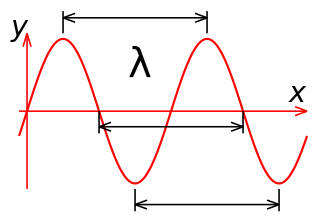
In physics, the wavelength is the spatial period of a periodic wave—the distance over which the wave's shape repeats. It is the distance between consecutive corresponding points of the same phase on the wave, such as two adjacent crests, troughs, or zero crossings, and is a characteristic of both traveling waves and standing waves, as well as other spatial wave patterns. The inverse of the wavelength is called the spatial frequency. Wavelength is commonly designated by the Greek letter lambda (λ). The term wavelength is also sometimes applied to modulated waves, and to the sinusoidal envelopes of modulated waves or waves formed by interference of several sinusoids.
The Schrödinger equation is a linear partial differential equation that governs the wave function of a quantum-mechanical system. It is a key result in quantum mechanics, and its discovery was a significant landmark in the development of the subject. The equation is named after Erwin Schrödinger, who postulated the equation in 1925, and published it in 1926, forming the basis for the work that resulted in his Nobel Prize in Physics in 1933.
In physics, Bragg's law, or Wulff–Bragg's condition, a special case of Laue diffraction, gives the angles for coherent and incoherent scattering from a crystal lattice. When X-rays are incident on an atom, they make the electronic cloud move, as does any electromagnetic wave. The movement of these charges re-radiates waves with the same frequency, blurred slightly due to a variety of effects; this phenomenon is known as Rayleigh scattering. The scattered waves can themselves be scattered but this secondary scattering is assumed to be negligible.
In optics, the Fraunhofer diffraction equation is used to model the diffraction of waves when the diffraction pattern is viewed at a long distance from the diffracting object, and also when it is viewed at the focal plane of an imaging lens. In contrast, the diffraction pattern created near the object is given by the Fresnel diffraction equation.
A rotational transition is an abrupt change in angular momentum in quantum physics. Like all other properties of a quantum particle, angular momentum is quantized, meaning it can only equal certain discrete values, which correspond to different rotational energy states. When a particle loses angular momentum, it is said to have transitioned to a lower rotational energy state. Likewise, when a particle gains angular momentum, a positive rotational transition is said to have occurred.
In optics, the Fresnel diffraction equation for near-field diffraction is an approximation of the Kirchhoff–Fresnel diffraction that can be applied to the propagation of waves in the near field. It is used to calculate the diffraction pattern created by waves passing through an aperture or around an object, when viewed from relatively close to the object. In contrast the diffraction pattern in the far field region is given by the Fraunhofer diffraction equation.
In physics, a Bragg plane is a plane in reciprocal space which bisects a reciprocal lattice vector, , at right angles. The Bragg plane is defined as part of the Von Laue condition for diffraction peaks in x-ray diffraction crystallography.
In quantum mechanics the delta potential is a potential well mathematically described by the Dirac delta function - a generalized function. Qualitatively, it corresponds to a potential which is zero everywhere, except at a single point, where it takes an infinite value. This can be used to simulate situations where a particle is free to move in two regions of space with a barrier between the two regions. For example, an electron can move almost freely in a conducting material, but if two conducting surfaces are put close together, the interface between them acts as a barrier for the electron that can be approximated by a delta potential.
Photon polarization is the quantum mechanical description of the classical polarized sinusoidal plane electromagnetic wave. An individual photon can be described as having right or left circular polarization, or a superposition of the two. Equivalently, a photon can be described as having horizontal or vertical linear polarization, or a superposition of the two.
In mathematics, the spectral theory of ordinary differential equations is the part of spectral theory concerned with the determination of the spectrum and eigenfunction expansion associated with a linear ordinary differential equation. In his dissertation Hermann Weyl generalized the classical Sturm–Liouville theory on a finite closed interval to second order differential operators with singularities at the endpoints of the interval, possibly semi-infinite or infinite. Unlike the classical case, the spectrum may no longer consist of just a countable set of eigenvalues, but may also contain a continuous part. In this case the eigenfunction expansion involves an integral over the continuous part with respect to a spectral measure, given by the Titchmarsh–Kodaira formula. The theory was put in its final simplified form for singular differential equations of even degree by Kodaira and others, using von Neumann's spectral theorem. It has had important applications in quantum mechanics, operator theory and harmonic analysis on semisimple Lie groups.
The Kapitza–Dirac effect is a quantum mechanical effect consisting of the diffraction of matter by a standing wave of light. The effect was first predicted as the diffraction of electrons from a standing wave of light by Paul Dirac and Pyotr Kapitsa in 1933. The effect relies on the wave–particle duality of matter as stated by the de Broglie hypothesis in 1924.
In fluid dynamics, the Oseen equations describe the flow of a viscous and incompressible fluid at small Reynolds numbers, as formulated by Carl Wilhelm Oseen in 1910. Oseen flow is an improved description of these flows, as compared to Stokes flow, with the (partial) inclusion of convective acceleration.
In fluid dynamics, a cnoidal wave is a nonlinear and exact periodic wave solution of the Korteweg–de Vries equation. These solutions are in terms of the Jacobi elliptic function cn, which is why they are coined cnoidal waves. They are used to describe surface gravity waves of fairly long wavelength, as compared to the water depth.
Quantum mechanics was first applied to optics, and interference in particular, by Paul Dirac. Richard Feynman, in his Lectures on Physics, uses Dirac's notation to describe thought experiments on double-slit interference of electrons. Feynman's approach was extended to N-slit interferometers for either single-photon illumination, or narrow-linewidth laser illumination, that is, illumination by indistinguishable photons, by Frank Duarte. The N-slit interferometer was first applied in the generation and measurement of complex interference patterns.
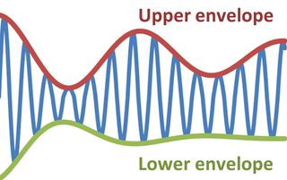
In physics and engineering, the envelope of an oscillating signal is a smooth curve outlining its extremes. The envelope thus generalizes the concept of a constant amplitude into an instantaneous amplitude. The figure illustrates a modulated sine wave varying between an upper and a lower envelope. The envelope function may be a function of time, space, angle, or indeed of any variable.
In optics, the Fraunhofer diffraction equation is used to model the diffraction of waves when the diffraction pattern is viewed at a long distance from the diffracting object, and also when it is viewed at the focal plane of an imaging lens.
In quantum mechanics, universality is the observation that there are properties for a large class of systems that are independent of the exact structural details of the system. The notion of universality is familiar in the study and application of statistical mechanics to various physical systems since its introduction in a very precise fashion by Leo Kadanoff. Although not quite the same, it is closely related to universality as applied to quantum systems. This concept links to the essence of renormalization and scaling in many problems. Renormalization is based on the notion that a measurement device of wavelength is insensitive to details of structure at distances much smaller than . An important consequence of universality is that one can mimic the real short-structure distance of the measurement device and the system to be measured by simple short-distance structure. Even though it is seen that scaling, universality and renormalization are closely related, they are not to be used interchangeably.
In physics and engineering, the radiative heat transfer from one surface to another is the equal to the difference of incoming and outgoing radiation from the first surface. In general, the heat transfer between surfaces is governed by temperature, surface emissivity properties and the geometry of the surfaces. The relation for heat transfer can be written as an integral equation with boundary conditions based upon surface conditions. Kernel functions can be useful in approximating and solving this integral equation.
This page is based on this Wikipedia article Text is available under the CC BY-SA 4.0 license; additional terms may apply. Images, videos and audio are available under their respective licenses.