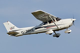
An aircraft is a vehicle that is able to fly by gaining support from the air. It counters the force of gravity by using either static lift or the dynamic lift of an airfoil, or, in a few cases, direct downward thrust from its engines. Common examples of aircraft include airplanes, helicopters, airships, gliders, paramotors, and hot air balloons.

A jet engine is a type of reaction engine, discharging a fast-moving jet of heated gas that generates thrust by jet propulsion. While this broad definition may include rocket, water jet, and hybrid propulsion, the term jet engine typically refers to an internal combustion air-breathing jet engine such as a turbojet, turbofan, ramjet, pulse jet, or scramjet. In general, jet engines are internal combustion engines.

Thrust is a reaction force described quantitatively by Newton's third law. When a system expels or accelerates mass in one direction, the accelerated mass will cause a force of equal magnitude but opposite direction to be applied to that system. The force applied on a surface in a direction perpendicular or normal to the surface is also called thrust. Force, and thus thrust, is measured using the International System of Units (SI) in newtons, and represents the amount needed to accelerate 1 kilogram of mass at the rate of 1 meter per second per second. In mechanical engineering, force orthogonal to the main load is referred to as static thrust.

Propulsion is the generation of force by any combination of pushing or pulling to modify the translational motion of an object, which is typically a rigid body but may also concern a fluid. The term is derived from two Latin words: pro, meaning before or forward; and pellere, meaning to drive. A propulsion system consists of a source of mechanical power, and a propulsor.

A turbofan or fanjet is a type of airbreathing jet engine that is widely used in aircraft propulsion. The word "turbofan" is a combination of references to the preceding generation engine technology of the turbojet and the additional fan stage. It consists of a gas turbine engine which achieves mechanical energy from combustion, and a ducted fan that uses the mechanical energy from the gas turbine to force air rearwards. Thus, whereas all the air taken in by a turbojet passes through the combustion chamber and turbines, in a turbofan some of that air bypasses these components. A turbofan thus can be thought of as a turbojet being used to drive a ducted fan, with both of these contributing to the thrust.

Flight or flying is the process by which an object moves through a space without contacting any planetary surface, either within an atmosphere or through the vacuum of outer space. This can be achieved by generating aerodynamic lift associated with gliding or propulsive thrust, aerostatically using buoyancy, or by ballistic movement.

The turbojet is an airbreathing jet engine which is typically used in aircraft. It consists of a gas turbine with a propelling nozzle. The gas turbine has an air inlet which includes inlet guide vanes, a compressor, a combustion chamber, and a turbine. The compressed air from the compressor is heated by burning fuel in the combustion chamber and then allowed to expand through the turbine. The turbine exhaust is then expanded in the propelling nozzle where it is accelerated to high speed to provide thrust. Two engineers, Frank Whittle in the United Kingdom and Hans von Ohain in Germany, developed the concept independently into practical engines during the late 1930s.

An ornithopter is an aircraft that flies by flapping its wings. Designers sought to imitate the flapping-wing flight of birds, bats, and insects. Though machines may differ in form, they are usually built on the same scale as flying animals. Larger, crewed ornithopters have also been built and some have been successful. Crewed ornithopters are generally powered either by engines or by the pilot.

In aeronautics, a ducted fan is a thrust-generating mechanical fan or propeller mounted within a cylindrical duct or shroud. Other terms include ducted propeller or shrouded propeller. When used in vertical takeoff and landing (VTOL) applications it is also known as a shrouded rotor.

The bypass ratio (BPR) of a turbofan engine is the ratio between the mass flow rate of the bypass stream to the mass flow rate entering the core. A 10:1 bypass ratio, for example, means that 10 kg of air passes through the bypass duct for every 1 kg of air passing through the core.
Thrust vectoring, also known as thrust vector control (TVC), is the ability of an aircraft, rocket or other vehicle to manipulate the direction of the thrust from its engine(s) or motor(s) to control the attitude or angular velocity of the vehicle.

A conventional fixed-wing aircraft flight control system (AFCS) consists of flight control surfaces, the respective cockpit controls, connecting linkages, and the necessary operating mechanisms to control an aircraft's direction in flight. Aircraft engine controls are also considered flight controls as they change speed.

Elevators are flight control surfaces, usually at the rear of an aircraft, which control the aircraft's pitch, and therefore the angle of attack and the lift of the wing. The elevators are usually hinged to the tailplane or horizontal stabilizer. They may be the only pitch control surface present, and are sometimes located at the front of the aircraft or integrated into a rear "all-moving tailplane", also called a slab elevator or stabilator.
A jet engine performs by converting fuel into thrust. How well it performs is an indication of what proportion of its fuel goes to waste. It transfers heat from burning fuel to air passing through the engine. In doing so it produces thrust work when propelling a vehicle but a lot of the fuel is wasted and only appears as heat. Propulsion engineers aim to minimize the degradation of fuel energy into unusable thermal energy. Increased emphasis on performance improvements for commercial airliners came in the 1970s from the rising cost of fuel.

A rotary-wing aircraft, rotorwing aircraft or rotorcraft is a heavier-than-air aircraft with rotary wings that spin around a vertical mast to generate lift. The assembly of several rotor blades mounted on a single mast is referred to as a rotor. The International Civil Aviation Organization (ICAO) defines a rotorcraft as "supported in flight by the reactions of the air on one or more rotors".
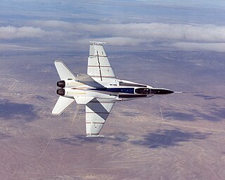
The X-53 Active Aeroelastic Wing (AAW) development program is a completed American research project that was undertaken jointly by the Air Force Research Laboratory (AFRL), Boeing Phantom Works and NASA's Dryden Flight Research Center, where the technology was flight tested on a modified McDonnell Douglas F/A-18 Hornet. Active Aeroelastic Wing Technology is a technology that integrates wing aerodynamics, controls, and structure to harness and control wing aeroelastic twist at high speeds and dynamic pressures. By using multiple leading and trailing edge controls like "aerodynamic tabs", subtle amounts of aeroelastic twist can be controlled to provide large amounts of wing control power, while minimizing maneuver air loads at high wing strain conditions or aerodynamic drag at low wing strain conditions. This program was the first full-scale proof of AAW technology.
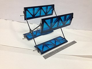
The propulsive wing is a patented UAV design concept developed in the 2000s with extremely high lift and internal volume. The propulsive wing could be used to develop a new class of aircraft based on an embedded, distributed cross-flow fan propulsion system within a thick wing. The fan, partially embedded within the airfoil section, draws the flow in from the suction surface and exhausts at the trailing edge. In cruise, the combination of distributed boundary-layer ingestion and wake filling increase propulsive efficiency, while distributed vectored thrust provides substantial improvements in pressure drag.

The fuel economy in aircraft is the measure of the transport energy efficiency of aircraft. Fuel efficiency is increased with better aerodynamics and by reducing weight, and with improved engine brake-specific fuel consumption and propulsive efficiency or thrust-specific fuel consumption. Endurance and range can be maximized with the optimum airspeed, and economy is better at optimum altitudes, usually higher. An airline efficiency depends on its fleet fuel burn, seating density, air cargo and passenger load factor, while operational procedures like maintenance and routing can save fuel.
A cyclorotor, cycloidal rotor, cycloidal propeller or cyclogiro, is a fluid propulsion device that converts shaft power into the acceleration of a fluid using a rotating axis perpendicular to the direction of fluid motion. It uses several blades with a spanwise axis parallel to the axis of rotation and perpendicular to the direction of fluid motion. These blades are cyclically pitched twice per revolution to produce force in any direction normal to the axis of rotation. Cyclorotors are used for propulsion, lift, and control on air and water vehicles. An aircraft using cyclorotors as the primary source of lift, propulsion, and control is known as a cyclogyro or cyclocopter. A unique aspect is that it can change the magnitude and direction of thrust without the need of tilting any aircraft structures. The patented application, used on ships with particular actuation mechanisms both mechanical or hydraulic, is named after German company Voith Turbo.

