Electro-pneumatic brake system on British railway trains

Last updated

The electro-pneumatic brake system on British mainline railway trains was introduced in 1950 and remains the primary braking system for multiple units in service today, although London Transport underground trains had been fitted with EP brakes since the 1920s. The Southern Region of British Railways operated a self-contained fleet of electric multiple units for suburban and middle-distance passenger trains. From 1950, an expansion of the fleet was undertaken and the new build adopted a braking system that was novel in the UK, the electro-pneumatic brake in which compressed air brake operation was controlled electrically by the driver. This was a considerable and successful technical advance, enabling a quicker and more sensitive response to the driver's operation of brake controls.

Contents

Origins

From the 1920s, the Southern Railway of the UK and its predecessor companies had adopted electrification and multiple-unit train operation as a solution for dense and intensive passenger service requirements. The fleet prior to World War II used the two-pipe Westinghouse Air Brake system, which was more effective than the generally prevailing vacuum brake then in favour in the UK. However it had disadvantages, chiefly:

The First EP-fitted units

The first Southern units fitted with EP brake could be considered the Bulleid double deck 4-DDs built 1949 (4001 & 4002). The EP brake fitted to this stock was not of the self lapping type and still required the Westinghouse brake as the 'fail to safe' braking as the EP brake fitted was of the 'energise to apply' type, which meant if there was a loss of brake control voltage the EP brake was inoperative. The 4-DDs were based on the earlier 4-SUB but were not operationally compatible with either the 4-SUB or later EPB stock.

Starting in 1950, a large new fleet of suburban multiple units was delivered to a pre-war design and, as well as other technical improvements, they were equipped with the electro-pneumatic brake – universally referred to as "the EP brake". The advance in braking technology dominated the other developments and the designation of the train units was 2-EPB and 4-EPB for the two- and four-car units respectively. The design was successful and a larger fleet of broadly similar design was built and the Kent Coast Line electrification extended the adoption of the EP brake to medium distance passenger operation but still confined to multiple units. (A small fleet of locomotives were built for the Southern Region and had a brake control system fitted that was compatible for interoperability purposes.)

Westinghouse and EP brake operation

The trains had Westinghouse brake equipment and had an electric control system, activating the compressed air brakes on each coach. In normal operation, the driver used the EP system exclusively but it was not fail-safe. If the electrical system failed, the driver merely had to move the brake valve to a further position and the same valve operated the fail-safe Westinghouse system on the train. This was only done in case of failure or emergency.

The Westinghouse system uses air reservoirs on each vehicle and compressed air is released from these reservoirs to the brake cylinders as the pressure in the train pipe is reduced by the driver operating the brake valve. This process causes a mechanical linkage to press the brake blocks against the wheels.

The release of compressed air into the brake cylinders is achieved by triple valves, which are themselves controlled by the pressure of air in the train pipe, a pneumatic pipe running the length of the train. When the driver wishes to make a brake application, he operates the driver's brake valve which releases some air from the train pipe, so operating the triple valves. When the driver wishes to release the brakes, his operation of the driver's brake valve returns compressed air (stored in a cylinder near the driving position) into the train pipe and this moves the triple valve so as to release the air in the brake cylinders to atmosphere, allowing the brake blocks to move clear of the wheels. Although, in multiple-unit operation, the air reservoirs on the vehicles can be relatively quickly charged, the restoration of pressure to the train pipe takes some time as air has to travel physically down the length of the train.

In EP operation, a distributor, performing functions similar to those of the triple valve, is operated directly and instantly by electrical control from the driver's brake valve. The Westinghouse brake cylinders and air reservoirs and pumps are used, so that only the means of transmitting the driver's command is changed.

Advantages and developments

The advantages of the EP system are that:

The electrical control system required control cables throughout the length of the train (in addition to the two air pipes for Westinghouse operation) and a jumper cable was provided at each end of every unit for use when two or more units were coupled to run in multiple. In 1950, no electronic control was possible and the system used four conductors in the cable to achieve graduated braking rates.

The EP brake system was greatly appreciated by drivers and was adopted for subsequent builds of rolling stock on the Southern Region of British Railways, including middle-distance passenger stock.

The next generation

Driver's brake handle on a Class 317 Electric Multiple Unit Davis Metcalfe Brake Handle.jpg
Driver's brake handle on a Class 317 Electric Multiple Unit

Following on from the original EP stock, the system was developed further on the second generation of Multiple Unit trains built for British Rail in the 1970s such as the Class 313 EMU.

The Westinghouse air system was abandoned in favour of a fully electrical system of control, so that the need for a brake pipe and triple-valves was dispensed with. Instead a single air pipe, now called the main reservoir pipe runs the length of the train. It operates at 10 bar and in addition to feeding each brake cylinder reservoir also provides air for the secondary suspension systems (air bags) and power doors.

Each brake reservoir stores air at a pressure of 7 bar and is fed via a pressure reducing valve off the main reservoir pipe. The driver's brake handle passes control voltages down three wires to each EP control valve, which allows air from the brake reservoir to pass into the brake cylinder, thereby activating the disc brake. The presence of the voltage holds the brakes off, providing a fail safe system.

The 3 step "Westcode" brake uses three wires and these operate in a binary sequence to control the brake step. 10 & 11 are the brake coding to provide the 3 steps, 12 wire is emergency brake, 15 wire is EP brake negative.

Positions on the brake handle are:

This system remains in use today.

Brake continuity wire

On the previous EP brake systems, if the train divided or a serious air leak occurred the drop in brake pipe pressure automatically caused the brakes to apply. This feature was lost with the removal of the brake pipe, so an electronic equivalent was created.

The brake continuity wire (a.k.a. trainwire 13) is fed with a 120 V DC control voltage from the battery and runs in a loop round the train, passing through various governors (air pressure operated electrical switches) in each carriage, finally feeding the power and brake control handle(s) in the driver's desk. If any of the governors should open due to low air pressure, or if the Brake Continuity Wire itself should be broken by the train dividing, the control voltage to the driver's desk will be cut off causing traction power to the motors to be removed and the emergency brake [1] to be applied.

Current use

In the UK the most recently built Multiple Units such as the Alstom Aventra family still use friction (disc) brakes which are operated by electro-pneumatic valves for their primary braking system. Additionally dynamic braking is blended with this to achieve a higher braking force and reduce brake pad wear.

See also

Related Research Articles

<span class="mw-page-title-main">George Westinghouse</span> American engineer and businessman (1846–1912)

George Westinghouse Jr. was an American entrepreneur and engineer based in Pennsylvania who created the railway air brake and was a pioneer of the electrical industry, receiving his first patent at the age of 19. Westinghouse saw the potential of using alternating current for electric power distribution in the early 1880s and put all his resources into developing and marketing it. This put Westinghouse's business in direct competition with Thomas Edison, who marketed direct current for electric power distribution. In 1911 Westinghouse received the American Institute of Electrical Engineers's (AIEE) Edison Medal "For meritorious achievement in connection with the development of the alternating current system." He founded the Westinghouse Electric Corporation in 1886.

<span class="mw-page-title-main">Railway air brake</span> Fail-safe power braking system with compressed air as the operating medium

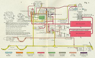
A railway air brake is a railway brake power braking system with compressed air as the operating medium. Modern trains rely upon a fail-safe air brake system that is based upon a design patented by George Westinghouse on April 13, 1869. The Westinghouse Air Brake Company was subsequently organized to manufacture and sell Westinghouse's invention. In various forms, it has been nearly universally adopted.

<span class="mw-page-title-main">Pneumatics</span> Branch of engineering

Pneumatics is a branch of engineering that makes use of gas or pressurized air.

<span class="mw-page-title-main">Vacuum brake</span> Train braking system

The vacuum brake is a braking system employed on trains and introduced in the mid-1860s. A variant, the automatic vacuum brake system, became almost universal in British train equipment and in countries influenced by British practice. Vacuum brakes also enjoyed a brief period of adoption in the United States, primarily on narrow-gauge railroads. Their limitations caused them to be progressively superseded by compressed air systems starting in the United Kingdom from the 1970s onward. The vacuum brake system is now obsolete; it is not in large-scale usage anywhere in the world, other than in South Africa, largely supplanted by air brakes.

Compressed air is air kept under a pressure that is greater than atmospheric pressure. Compressed air is an important medium for transfer of energy in industrial processes, and is used for power tools such as air hammers, drills, wrenches, and others, as well as to atomize paint, to operate air cylinders for automation, and can also be used to propel vehicles. Brakes applied by compressed air made large railway trains safer and more efficient to operate. Compressed air brakes are also found on large highway vehicles.

<span class="mw-page-title-main">Fluid power</span> Use of fluids under pressure to generate, control, and transmit power

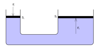
Fluid power is the use of fluids under pressure to generate, control, and transmit power. Fluid power is conventionally subdivided into hydraulics and pneumatics. Although steam is also a fluid, steam power is usually classified separately from fluid power. Compressed-air and water-pressure systems were once used to transmit power from a central source to industrial users over extended geographic areas; fluid power systems today are usually within a single building or mobile machine.

Rail terminology is a form of technical terminology. The difference between the American term railroad and the international term railway is the most significant difference in rail terminology. These and other terms have often originated from the parallel development of rail transport systems in different parts of the world. In English-speaking countries outside the United Kingdom, a mixture of US and UK terms may exist.

<span class="mw-page-title-main">Steam locomotive components</span> Glossary of the main components of a typical steam locomotive

Main components found on a typical steam locomotive include:

<span class="mw-page-title-main">Railway brake</span> Component of railway rolling stock

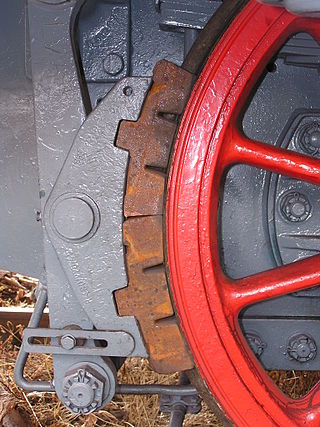
A railway brake is a type of brake used on the cars of railway trains to enable deceleration, control acceleration (downhill) or to keep them immobile when parked. While the basic principle is similar to that on road vehicle usage, operational features are more complex because of the need to control multiple linked carriages and to be effective on vehicles left without a prime mover. Clasp brakes are one type of brakes historically used on trains.

An exhaust brake is a means of slowing a diesel engine by closing off the exhaust path from the engine, causing the exhaust gases to be compressed in the exhaust manifold, and in the cylinder. Since the exhaust is being compressed, and there is no fuel being applied, the engine slows down the vehicle. The amount of negative torque generated is usually directly proportional to the back pressure of the engine.

<span class="mw-page-title-main">Westinghouse Air Brake Company</span> Former American manufacturing company

The Westinghouse Air Brake Company was founded on September 28, 1869 by George Westinghouse in Pittsburgh, Pennsylvania. Earlier in the year he had invented the railway air brake in New York state.

The electro-pneumatic action is a control system by the mean of air pressure for pipe organs, whereby air pressure, controlled by an electric current and operated by the keys of an organ console, opens and closes valves within wind chests, allowing the pipes to speak. This system also allows the console to be physically detached from the organ itself. The only connection was via an electrical cable from the console to the relay, with some early organ consoles utilizing a separate wind supply to operate combination pistons.

<span class="mw-page-title-main">FS Class E.636</span> Locomotive class

The FS E.636 is a class of Italian articulated electric locomotives. They were introduced in the course of the 1940s until the 1960s, and have been decommissioned since 2006. They have been one of the most numerous Italian locomotive groups, and have been widely employed during their long career, hauling every type of train, ranging from freight to long range passenger services. Their introduction also saw the employment of some revolutionary design concepts, such as the articulated carbody and the three bogies scheme.

<span class="mw-page-title-main">Air brake (road vehicle)</span> Type of friction brake for vehicles

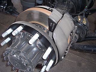
An air brake or, more formally, a compressed-air-brake system, is a type of friction brake for vehicles in which compressed air pressing on a piston is used to apply the pressure to the brake pad or brake shoe needed to stop the vehicle. Air brakes are used in large heavy vehicles, particularly those having multiple trailers which must be linked into the brake system, such as trucks, buses, trailers, and semi-trailers, in addition to their use in railroad trains. George Westinghouse first developed air brakes for use in railway service. He patented a safer air brake on March 5, 1872. Westinghouse made numerous alterations to improve his air pressured brake invention, which led to various forms of the automatic brake. In the early 20th century, after its advantages were proven in railway use, it was adopted by manufacturers of trucks and heavy road vehicles.

<span class="mw-page-title-main">Meillerwagen</span> Motor vehicle

The Meillerwagen was a German World War II trailer used to transport a V-2 rocket from the 'transloading point' of the Technical Troop Area to the launching point, to erect the missile on the Brennstand, and to act as the service gantry for fuelling and launch preparation.

<span class="mw-page-title-main">Brake-by-wire</span> Automotive technology

Brake-by-wire technology in the automotive industry is the ability to control brakes through electronic means, without a mechanical connection that transfers force to the physical braking system from a driver input apparatus such as a pedal or lever.

Electronically controlled pneumatic brakes are a type of railway braking systems.

<span class="mw-page-title-main">South African Class 6E1, Series 1</span>

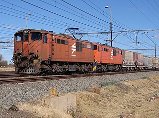
The South African Railways Class 6E1, Series 1 of 1969 was an electric locomotive.

<span class="mw-page-title-main">South African Class 18E, Series 1</span>

The Spoornet Class 18E, Series 1 of 2000 is a South African electric locomotive.

<span class="mw-page-title-main">Decelostat</span> Railroad wheel slide protection braking system

Decelostat is a wheel slide protection system developed by Westinghouse Air Brake Company that is used in railroad cars to prevent over-braking that causes wheel-slide, a condition of reduction in friction between train wheels and rails. This low wheel/rail adhesion condition reduces braking performance and causes damage to wheels and the rails.

References

  1. "Braking Principles for Rail Vehicles Section 7.4 Emergency Brake control". RSSB. Retrieved 22 April 2019.[ permanent dead link ]

Further reading