An exhaust brake is a means of slowing a diesel engine by closing off the exhaust path from the engine, causing the exhaust gases to be compressed in the exhaust manifold, and in the cylinder. Since the exhaust is being compressed, and there is no fuel being applied, the engine slows down the vehicle: the crankshaft and hence the wheels work against the pistons to compress the exhaust. The amount of braking torque generated is usually directly proportional to the back pressure of the engine.
Exhaust brakes are manufactured by many companies. The brakes vary in design, but essentially operate as described above. More advanced exhaust brakes have exhaust pressure modulation (EPM) that controls the back pressure which in turn improves the braking performance across a range of engine speeds.
Description
An exhaust brake is a valve which essentially creates a back-pressure in the exhaust system, which applies enough force onto the engine's pistons to slow the engine. In most cases, an exhaust brake is so effective that it can slow a heavily-loaded vehicle on a downgrade without ever applying the vehicle’s service brakes. Under these conditions, the exhaust flow from the cylinders is bottlenecked and rapidly builds pressure in the exhaust system upstream from the exhaust brake. Depending on engine speed, this can easily reach up to 60psi (410kPa) maximum working pressure. Maximum working pressure is limited as part of the design of an exhaust brake. In this example, that same 60 psi also remains in the cylinder for the entire exhaust stroke (exhaust valve open) and exerts 60 psi on the piston top to resist its upward movement. This produces a negative torque, slowing the engine for a braking effect.
Some innovations increase the exhaust back-pressure by various means, leading to more torque at the flywheel, and therefore more braking power. Braking effectiveness is measured in units of power and is about 60 to 80% of the engine's maximum power output. More performance can be achieved by down shifting the vehicle (increasing the leverage, or gear ratio of the engine over the wheels). See also Jake brake, a popular compression brake.
Sound
A compression brake, a form of engine brake, produces greater noise than an exhaust brake. For this reason, some vehicle original equipment manufacturers prefer to use an exhaust brake despite its lower braking power. Combining compression braking with exhaust braking[how?] can increase effectiveness without being as loud as a compression brake alone.
Numerous jurisdictions ban the use of an unmuffled compression brake.
Pedal-operated butterfly valve
The butterfly valve is made up of metal made in a circular shape, having three peripheral circular cuts on it. These circular cuts are made because it is not expected to block the whole cross section of the exhaust pipe. If there were no holes, the engine would stop instead of slowing down.
The butterfly valve is actuated through hydraulic linkages. This consists of a hydraulic pressure pump which is connected to the butterfly valve. This pump controls the operation of butterfly valve in following manner: When brakes are applied by the driver, the cylinder reduces its pressure so that the valve closes and restricts the path of exhaust gases. In this position the butterfly valve remains perpendicular to the flow of exhaust gases and thus creates back pressure on the engine. The butterfly valve has one to three holes in it so that there is not a complete blockage of the exhaust pipe. This assures the avoidance of damage due to high pressure.
When the brakes are released by the driver, the cylinder generates pressure so that the butterfly valve is opened and allows the exhaust gases to flow into the exhaust pipe. In this position the butterfly valve remains parallel to the path of exhaust gases and thus releases the pressure on the engine and allows its speed to increase.
Two-stage pressure control
Increase in the back pressure with the help of a butterfly valve can also be achieved by operating in two stages i.e. two valves can be used. This also ensures the efficient working of the valve and increase longevity by avoiding valve failure. Such type of arrangement is found to be very useful in the case of heavy duty trucks. To create sufficient back pressure to reduce the engine speed, it requires a large force from the valve which is made possible by a two-valve arrangement.
ARIS actuator valve
Usually pneumatic or hydraulic actuators are used to operate the butterfly valve, but with the large force of exhaust gases this type of actuator turns out to be inefficient, hence the ARIS type of valve actuator which is widely used in the industry and provides effective valve-operating force.
Images
Variable exhaust brake
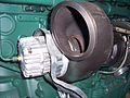
Exhaust brake & turbo assembly
Exhaust brake shutter assembly
References
Ma, J., Chen, Y., Yu, Q., Guo, R.: Distance control for automotive’s stopping with retarder.
China Journal of Highway and Transport 16(1), 108–112 (2003) (in Chinese)
Chengye Liu1 and Jianming Shen: Effect of Turbocharging on Exhaust Brake Performance in an Automobile (2003)
This page is based on this Wikipedia article Text is available under the CC BY-SA 4.0 license; additional terms may apply. Images, videos and audio are available under their respective licenses.