
A magnetic field is a physical field that describes the magnetic influence on moving electric charges, electric currents, and magnetic materials. A moving charge in a magnetic field experiences a force perpendicular to its own velocity and to the magnetic field. A permanent magnet's magnetic field pulls on ferromagnetic materials such as iron, and attracts or repels other magnets. In addition, a nonuniform magnetic field exerts minuscule forces on "nonmagnetic" materials by three other magnetic effects: paramagnetism, diamagnetism, and antiferromagnetism, although these forces are usually so small they can only be detected by laboratory equipment. Magnetic fields surround magnetized materials, electric currents, and electric fields varying in time. Since both strength and direction of a magnetic field may vary with location, it is described mathematically by a function assigning a vector to each point of space, called a vector field.

Electromagnetic or magnetic induction is the production of an electromotive force (emf) across an electrical conductor in a changing magnetic field.

An electric motor is a machine that converts electrical energy into mechanical energy. Most electric motors operate through the interaction between the motor's magnetic field and electric current in a wire winding to generate force in the form of torque applied on the motor's shaft. An electric generator is mechanically identical to an electric motor, but operates in reverse, converting mechanical energy into electrical energy.
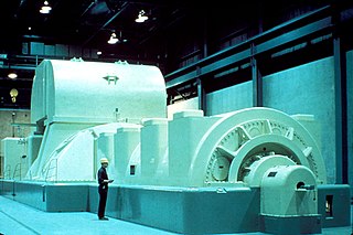
In electricity generation, a generator is a device that converts motion-based power or fuel-based power into electric power for use in an external circuit. Sources of mechanical energy include steam turbines, gas turbines, water turbines, internal combustion engines, wind turbines and even hand cranks. The first electromagnetic generator, the Faraday disk, was invented in 1831 by British scientist Michael Faraday. Generators provide nearly all the power for electrical grids.

A commutator is a rotary electrical switch in certain types of electric motors and electrical generators that periodically reverses the current direction between the rotor and the external circuit. It consists of a cylinder composed of multiple metal contact segments on the rotating armature of the machine. Two or more electrical contacts called "brushes" made of a soft conductive material like carbon press against the commutator, making sliding contact with successive segments of the commutator as it rotates. The windings on the armature are connected to the commutator segments.

An induction motor or asynchronous motor is an AC electric motor in which the electric current in the rotor that produces torque is obtained by electromagnetic induction from the magnetic field of the stator winding. An induction motor therefore needs no electrical connections to the rotor. An induction motor's rotor can be either wound type or squirrel-cage type.
A rotating magnetic field (RMF) is the resultant magnetic field produced by a system of coils symmetrically placed and supplied with polyphase currents. A rotating magnetic field can be produced by a poly-phase (two or more phases) current or by a single phase current provided that, in the latter case, two field windings are supplied and are so designed that the two resulting magnetic fields generated thereby are out of phase.
Polyphase coils are electromagnetic coils connected together in a polyphase system such as a generator or motor. In modern systems, the number of phases is usually three or a multiple of three. Each phase carries a sinusoidal alternating current whose phase is delayed relative to one of its neighbours and advanced relative to its other neighbour. The phase currents are separated in time evenly within each period of the alternating current. For example, in a three-phase system, the phases are separated from each other by one-third of the period.
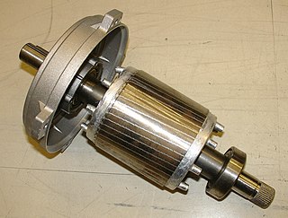
A squirrel-cage rotor is the rotating part of the common squirrel-cage induction motor. It consists of a cylinder of steel laminations, with aluminum or copper conductors embedded in its surface. In operation, the non-rotating stator winding is connected to an alternating current power source; the alternating current in the stator produces a rotating magnetic field. The rotor winding has current induced in it by the stator field, like a transformer except that the current in the rotor is varying at the stator field rotation rate minus the physical rotation rate. The interaction of the magnetic fields in the stator and the currents in the rotor produce a torque on the rotor.

The shaded-pole motor is the original type of AC single-phase motor, dating back to at least as early as 1890. A shaded-pole motor is a motor, in which the auxiliary winding is composed of a copper ring or bar surrounding a portion of each pole to produce a weakly rotating magnetic field. When single phase AC supply is applied to the stator winding, due to shading provided to the poles, a rotating magnetic field is generated. This auxiliary single-turn winding is called a shading coil. Currents induced in this coil by the magnetic field create a second electrical phase by delaying the phase of magnetic flux change for that pole enough to provide a 2-phase rotating magnetic field. The direction of rotation is from the unshaded side to the shaded (ring) side of the pole. Since the phase angle between the shaded and unshaded sections is small, shaded-pole motors produce only a small starting torque relative to torque at full speed. Shaded-pole motors of the asymmetrical type shown are only reversible by disassembly and flipping over the stator, though some similar looking motors have small, switch-shortable auxiliary windings of thin wire instead of thick copper bars and can reverse electrically. Another method of electrical reversing involves four coils.

Galileo Ferraris was an Italian university professor, physicist and electrical engineer, one of the pioneers of AC power system and inventor of the induction motor although he never patented his work. Many newspapers touted that his work on the induction motor and power transmission systems were some of the greatest inventions of all ages. He published an extensive and complete monograph on the experimental results obtained with open-circuit transformers of the type designed by the power engineers Lucien Gaulard and John Dixon Gibbs.

In electrical engineering, the armature is the winding of an electric machine which carries alternating current. The armature windings conduct AC even on DC machines, due to the commutator action or due to electronic commutation, as in brushless DC motors. The armature can be on either the rotor or the stator, depending on the type of electric machine.

A field coil is an electromagnet used to generate a magnetic field in an electro-magnetic machine, typically a rotating electrical machine such as a motor or generator. It consists of a coil of wire through which a current flows.

An AC motor is an electric motor driven by an alternating current (AC). The AC motor commonly consists of two basic parts, an outside stator having coils supplied with alternating current to produce a rotating magnetic field, and an inside rotor attached to the output shaft producing a second rotating magnetic field. The rotor magnetic field may be produced by permanent magnets, reluctance saliency, or DC or AC electrical windings.

The rotor is a moving component of an electromagnetic system in the electric motor, electric generator, or alternator. Its rotation is due to the interaction between the windings and magnetic fields which produces a torque around the rotor's axis.

A dynamo is an electrical generator that creates direct current using a commutator. Dynamos were the first electrical generators capable of delivering power for industry, and the foundation upon which many other later electric-power conversion devices were based, including the electric motor, the alternating-current alternator, and the rotary converter.
In electrical engineering, electric machine is a general term for machines using electromagnetic forces, such as electric motors, electric generators, and others. They are electromechanical energy converters: an electric motor converts electricity to mechanical power while an electric generator converts mechanical power to electricity. The moving parts in a machine can be rotating or linear. While transformers are occasionally called "static electric machines", since they do not have moving parts, generally they are not considered "machines", but as electrical devices "closely related" to the electrical machines.
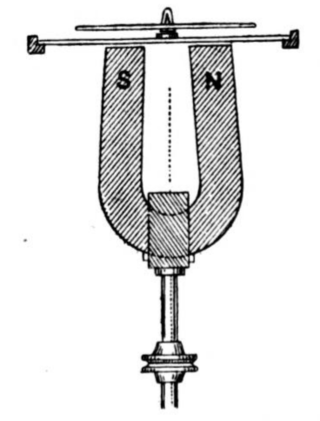
Arago's rotations is an observable magnetic phenomenon that involves the interactions between a magnetized needle and a moving metal disk. The effect was discovered by François Arago in 1824. At the time of their discovery, Arago's rotations were surprising effects that were difficult to explain. In 1831, Michael Faraday introduced the theory of electromagnetic induction, which explained how the effects happen in detail.
Walter Bailys Polyphase motor (1879) marks the beginning of the development of modern polyphase motors. Mr. Bailey exhibited his invention on the Physical Society of London on June 28, 1879, on the occasion of his reading a paper entitled, "A Mode of Producing Arago's Rotations."

