In physics and electrical engineering the reflection coefficient is a parameter that describes how much of an electromagnetic wave is reflected by an impedance discontinuity in the transmission medium. It is equal to the ratio of the amplitude of the reflected wave to the incident wave, with each expressed as phasors. For example, it is used in optics to calculate the amount of light that is reflected from a surface with a different index of refraction, such as a glass surface, or in an electrical transmission line to calculate how much of the electromagnetic wave is reflected by an impedance. The reflection coefficient is closely related to the transmission coefficient. The reflectance of a system is also sometimes called a "reflection coefficient".
In telecommunications, reflection loss occurs on a line which results in part of the energy being reflected back to the source. This can occur:
- At a discontinuity or impedance mismatch, e.g., in a transmission line, the ratio of the incident power to the reflected power. Reflection loss is usually expressed in dB.
- In an optical fiber, the loss that takes place at any discontinuity of refractive index, especially at an air-glass interface such as a fiber endface, at which a fraction of the optical signal is reflected back toward the source. This reflection phenomenon is also called "Fresnel reflection loss," or simply "Fresnel loss."
In telecommunications, return loss is the loss of power in the signal returned/reflected by a discontinuity in a transmission line or optical fiber. This discontinuity can be a mismatch with the terminating load or with a device inserted in the line. It is usually expressed as a ratio in decibels (dB);
In radio engineering and telecommunications, standing wave ratio (SWR) is a measure of impedance matching of loads to the characteristic impedance of a transmission line or waveguide. Impedance mismatches result in standing waves along the transmission line, and SWR is defined as the ratio of the partial standing wave's amplitude at an antinode (maximum) to the amplitude at a node (minimum) along the line.

A time-domain reflectometer (TDR) is an electronic instrument that uses time-domain reflectometry to characterize and locate faults in metallic cables. It can also be used to locate discontinuities in a connector, printed circuit board, or any other electrical path. The equivalent device for optical fiber is an optical time-domain reflectometer.
Signal reflection occurs when a signal is transmitted along a transmission medium, such as a copper cable or an optical fiber. Some of the signal power may be reflected back to its origin rather than being carried all the way along the cable to the far end. This happens because imperfections in the cable cause impedance mismatches and non-linear changes in the cable characteristics. These abrupt changes in characteristics cause some of the transmitted signal to be reflected. In radio frequency (RF) practice this is often measured in a dimensionless ratio known as voltage standing wave ratio (VSWR) with a VSWR bridge. The ratio of energy bounced back depends on the impedance mismatch. Mathematically, it is defined using the reflection coefficient.

In electronics, impedance matching is the practice of designing the input impedance of an electrical load or the output impedance of its corresponding signal source to maximize the power transfer or minimize signal reflection from the load.
In electronics, electrical termination is the practice of ending a transmission line with a device that matches the characteristic impedance of the line. This is intended to prevent signals from reflecting off the end of the transmission line. Reflections at the ends of unterminated transmission lines cause distortion which can produce ambiguous digital signal levels and mis-operation of digital systems. Reflections in analog signal systems cause such effects as video ghosting, or power loss in radio transmitter transmission lines.
Discontinuity may refer to:
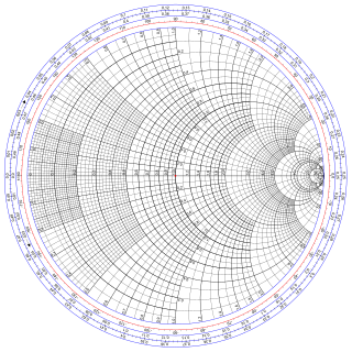
The Smith chart, invented by Phillip H. Smith (1905–1987), is a graphical aid or nomogram designed for electrical and electronics engineers specializing in radio frequency (RF) engineering to assist in solving problems with transmission lines and matching circuits. The Smith chart can be used to simultaneously display multiple parameters including impedances, admittances, reflection coefficients, scattering parameters, noise figure circles, constant gain contours and regions for unconditional stability, including mechanical vibrations analysis. The Smith chart is most frequently used at or within the unity radius region. However, the remainder is still mathematically relevant, being used, for example, in oscillator design and stability analysis.

Reflection is the change in direction of a wavefront at an interface between two different media so that the wavefront returns into the medium from which it originated. Common examples include the reflection of light, sound and water waves. The law of reflection says that for specular reflection the angle at which the wave is incident on the surface equals the angle at which it is reflected. Mirrors exhibit specular reflection.
The input impedance of an electrical network is the measure of the opposition to current (impedance), both static (resistance) and dynamic (reactance), into the load network that is external to the electrical source. The input admittance (1/impedance) is a measure of the load's propensity to draw current. The source network is the portion of the network that transmits power, and the load network is the portion of the network that consumes power.

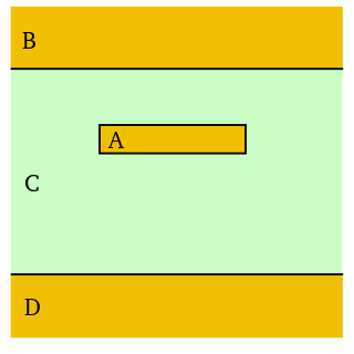
Microstrip is a type of electrical transmission line which can be fabricated using printed circuit board technology, and is used to convey microwave-frequency signals. It consists of a conducting strip separated from a ground plane by a dielectric layer known as the substrate. Microwave components such as antennas, couplers, filters, power dividers etc. can be formed from microstrip, with the entire device existing as the pattern of metallization on the substrate. Microstrip is thus much less expensive than traditional waveguide technology, as well as being far lighter and more compact. Microstrip was developed by ITT laboratories as a competitor to stripline.

In television, a ghost is a replica of the transmitted image, offset in position, that is super-imposed on top of the main image. It is often caused when a TV signal travels by two different paths to a receiving antenna, with a slight difference in timing.
An acoustic waveguide is a physical structure for guiding sound waves.
Stripline is a transverse electromagnetic (TEM) transmission line medium invented by Robert M. Barrett of the Air Force Cambridge Research Centre in the 1950s. Stripline is the earliest form of planar transmission line.
The transmission coefficient is used in physics and electrical engineering when wave propagation in a medium containing discontinuities is considered. A transmission coefficient describes the amplitude, intensity, or total power of a transmitted wave relative to an incident wave.
Time-domain reflectometry or TDR is a measurement technique used to determine the characteristics of electrical lines by observing reflected waveforms. Time-domain transmissometry (TDT) is an analogous technique that measures the transmitted impulse. Together, they provide a powerful means of analysing electrical or optical transmission media such as coaxial cable and optical fiber.
On-die termination (ODT) is the technology where the termination resistor for impedance matching in transmission lines is located inside a semiconductor chip instead of on a printed circuit board (PCB).