Related Research Articles
An electronic oscillator is an electronic circuit that produces a periodic, oscillating or alternating current (AC) signal, usually a sine wave, square wave or a triangle wave, powered by a direct current (DC) source. Oscillators are found in many electronic devices, such as radio receivers, television sets, radio and television broadcast transmitters, computers, computer peripherals, cellphones, radar, and many other devices.

An amplifier, electronic amplifier or (informally) amp is an electronic device that can increase the magnitude of a signal. It is a two-port electronic circuit that uses electric power from a power supply to increase the amplitude of a signal applied to its input terminals, producing a proportionally greater amplitude signal at its output. The amount of amplification provided by an amplifier is measured by its gain: the ratio of output voltage, current, or power to input. An amplifier is defined as a circuit that has a power gain greater than one.

In electronics, a comparator is a device that compares two voltages or currents and outputs a digital signal indicating which is larger. It has two analog input terminals and and one binary digital output . The output is ideally

In telecommunications, a repeater is an electronic device that receives a signal and retransmits it. Repeaters are used to extend transmissions so that the signal can cover longer distances or be received on the other side of an obstruction. Some types of repeaters broadcast an identical signal, but alter its method of transmission, for example, on another frequency or baud rate.

Audio crossovers are a type of electronic filter circuitry that splits an audio signal into two or more frequency ranges, so that the signals can be sent to loudspeaker drivers that are designed to operate within different frequency ranges. The crossover filters can be either active or passive. They are often described as two-way or three-way, which indicate, respectively, that the crossover splits a given signal into two frequency ranges or three frequency ranges. Crossovers are used in loudspeaker cabinets, power amplifiers in consumer electronics and pro audio and musical instrument amplifier products. For the latter two markets, crossovers are used in bass amplifiers, keyboard amplifiers, bass and keyboard speaker enclosures and sound reinforcement system equipment.

Audio system measurements are used to quantify audio system performance. These measurements are made for several purposes. Designers take measurements to specify the performance of a piece of equipment. Maintenance engineers make them to ensure equipment is still working to specification, or to ensure that the cumulative defects of an audio path are within limits considered acceptable. Audio system measurements often accommodate psychoacoustic principles to measure the system in a way that relates to human hearing.
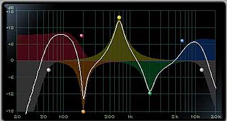
An audio filter is a frequency dependent circuit, working in the audio frequency range, 0 Hz to 20 kHz. Audio filters can amplify (boost), pass or attenuate (cut) some frequency ranges. Many types of filters exist for different audio applications including hi-fi stereo systems, musical synthesizers, effects units, sound reinforcement systems, instrument amplifiers and virtual reality systems.
A variable frequency oscillator (VFO) in electronics is an oscillator whose frequency can be tuned over some range. It is a necessary component in any tunable radio transmitter and in receivers that work by the superheterodyne principle. The oscillator controls the frequency to which the apparatus is tuned.
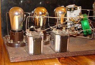
A tuned radio frequency receiver is a type of radio receiver that is composed of one or more tuned radio frequency (RF) amplifier stages followed by a detector (demodulator) circuit to extract the audio signal and usually an audio frequency amplifier. This type of receiver was popular in the 1920s. Early examples could be tedious to operate because when tuning in a station each stage had to be individually adjusted to the station's frequency, but later models had ganged tuning, the tuning mechanisms of all stages being linked together, and operated by just one control knob. By the mid 1930s, it was replaced by the superheterodyne receiver patented by Edwin Armstrong.
The 33-centimeter or 900 MHz band is a portion of the UHF radio spectrum internationally allocated to amateur radio on a secondary basis. It ranges from 902 to 928 MHz and is unique to ITU Region 2 (Americas). It is primarily used for very local communications as opposed to bands lower in frequency. However, very high antennas with high gain have shown 33 centimeters can provide good long-range communications almost equal to systems on lower frequencies such as the 70 centimeter band. The band is also used by industrial, scientific, and medical (ISM) equipment, as well as low-powered unlicensed devices. Amateur stations must accept harmful interference caused by ISM users but may receive protection from unlicensed devices.
Linear electronic oscillator circuits, which generate a sinusoidal output signal, are composed of an amplifier and a frequency selective element, a filter. A linear oscillator circuit which uses an RC network, a combination of resistors and capacitors, for its frequency selective part is called an RC oscillator.
A land mobile radio system (LMRS) is a person-to-person voice communication system consisting of two-way radio transceivers which can be stationary, mobile, or portable.
In electronics, motorboating is a type of low frequency parasitic oscillation that sometimes occurs in audio and radio equipment and often manifests itself as a sound similar to an idling motorboat engine, a "put-put-put", in audio output from speakers or earphones. It is a problem encountered particularly in radio transceivers and older vacuum tube audio systems, guitar amplifiers, PA systems and is caused by some type of unwanted feedback in the circuit. The amplifying devices in audio and radio equipment are vulnerable to a variety of feedback problems, which can cause distinctive noise in the output. The term motorboating is applied to oscillations whose frequency is below the range of hearing, from 1 to 10 hertz, so the individual oscillations are heard as pulses. Sometimes the oscillations can even be seen visually as the woofer cones in speakers slowly moving in and out.

An amateur radio repeater is an electronic device that receives a weak or low-level amateur radio signal and retransmits it at a higher level or higher power, so that the signal can cover longer distances without degradation. Many repeaters are located on hilltops or on tall buildings as the higher location increases their coverage area, sometimes referred to as the radio horizon, or "footprint". Amateur radio repeaters are similar in concept to those used by public safety entities, businesses, government, military, and more. Amateur radio repeaters may even use commercially packaged repeater systems that have been adjusted to operate within amateur radio frequency bands, but more often amateur repeaters are assembled from receivers, transmitters, controllers, power supplies, antennas, and other components, from various sources.
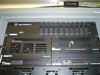
A radio repeater is a combination of a radio receiver and a radio transmitter that receives a signal and retransmits it, so that two-way radio signals can cover longer distances. A repeater sited at a high elevation can allow two mobile stations, otherwise out of line-of-sight propagation range of each other, to communicate. Repeaters are found in professional, commercial, and government mobile radio systems and also in amateur radio.
A cellular repeater is a type of bi-directional amplifier used to improve cell phone reception. A cellular repeater system commonly consists of a donor antenna that receives and transmits signal from nearby cell towers, coaxial cables, a signal amplifier, and an indoor rebroadcast antenna.
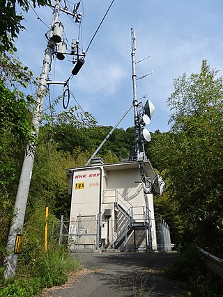
A broadcast relay station, also known as a satellite station, relay transmitter, broadcast translator (U.S.), re-broadcaster (Canada), repeater or complementary station (Mexico), is a broadcast transmitter which repeats the signal of a radio or television station to an area not covered by the originating station.
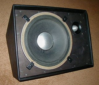
A stage monitor system is a set of performer-facing loudspeakers called monitor speakers, stage monitors, floor monitors, wedges, or foldbacks on stage during live music performances in which a sound reinforcement system is used to amplify a performance for the audience. The monitor system allows musicians to hear themselves and fellow band members clearly.
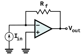
In electronics, a transimpedance amplifier (TIA) is a current to voltage converter, almost exclusively implemented with one or more operational amplifiers. The TIA can be used to amplify the current output of Geiger–Müller tubes, photo multiplier tubes, accelerometers, photo detectors and other types of sensors to a usable voltage. Current to voltage converters are used with sensors that have a current response that is more linear than the voltage response. This is the case with photodiodes where it is not uncommon for the current response to have better than 1% nonlinearity over a wide range of light input. The transimpedance amplifier presents a low impedance to the photodiode and isolates it from the output voltage of the operational amplifier. In its simplest form a transimpedance amplifier has just a large valued feedback resistor, Rf. The gain of the amplifier is set by this resistor and because the amplifier is in an inverting configuration, has a value of -Rf. There are several different configurations of transimpedance amplifiers, each suited to a particular application. The one factor they all have in common is the requirement to convert the low-level current of a sensor to a voltage. The gain, bandwidth, as well as current and voltage offsets change with different types of sensors, requiring different configurations of transimpedance amplifiers.

Equalization, or simply EQ, in sound recording and reproduction is the process of adjusting the volume of different frequency bands within an audio signal. The circuit or equipment used to achieve this is called an equalizer.
References
![]() This article incorporates public domain material from Federal Standard 1037C. General Services Administration. Archived from the original on 2022-01-22. (in support of MIL-STD-188).
This article incorporates public domain material from Federal Standard 1037C. General Services Administration. Archived from the original on 2022-01-22. (in support of MIL-STD-188).