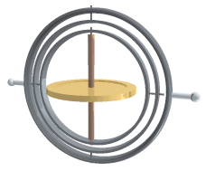
Gimbal-locked airplane. When the pitch (green) and yaw (magenta) gimbals become aligned, changes to roll (blue) and yaw apply the same rotation to the airplane.Adding a fourth rotational axis can solve the problem of gimbal lock, but it requires the outermost ring to be actively driven so that it stays 90 degrees out of alignment with the innermost axis (the flywheel shaft). Without active driving of the outermost ring, all four axes can become aligned in a plane as shown above, again leading to gimbal lock and inability to roll.
Gimbal lock is the loss of one degree of freedom in a multi-dimensional mechanism at certain alignments of the axes. In a three-dimensional three-gimbal mechanism, gimbal lock occurs when the axes of two of the gimbals are driven into a parallel configuration, "locking" the system into rotation in a degenerate two-dimensional space.
The term can be misleading in the sense that none of the individual gimbals is actually restrained. All three gimbals can still rotate freely about their respective axes of suspension. Nevertheless, because of the parallel orientation of two of the gimbals' axes, there is no gimbal available to accommodate rotation about one axis, leaving the suspended object effectively locked (i.e. unable to rotate) around that axis.
The problem can be generalized to other contexts, where a coordinate system loses definition of one of its variables at certain values of the other variables.
A gimbal is a ring that is suspended so it can rotate about an axis. Gimbals are typically nested one within another to accommodate rotation about multiple axes.
Some coordinate systems in mathematics behave as if they were real gimbals used to measure the angles, notably Euler angles.
For cases of three or fewer nested gimbals, gimbal lock inevitably occurs at some point in the system due to properties of covering spaces.
In engineering
While only two specific orientations produce exact gimbal lock, practical mechanical gimbals encounter difficulties near those orientations. When a set of gimbals is close to the locked configuration, small rotations of the gimbal platform require large motions of the surrounding gimbals. Although the ratio is infinite only at the point of gimbal lock, the practical speed and acceleration limits of the gimbals—due to inertia (resulting from the mass of each gimbal ring), bearing friction, the flow resistance of air or other fluid surrounding the gimbals (if they are not in a vacuum), and other physical and engineering factors—limit the motion of the platform close to that point.
In two dimensions
Gimbal lock can occur in gimbal systems with two degrees of freedom such as a theodolite with rotations about an azimuth (horizontal angle) and elevation (vertical angle). These two-dimensional systems can gimbal lock at zenith and nadir, because at those points azimuth is not well-defined, and rotation in the azimuth direction does not change the direction the theodolite is pointing.
Consider tracking a helicopter flying towards the theodolite from the horizon. The theodolite is a telescope mounted on a tripod so that it can move in azimuth and elevation to track the helicopter. The helicopter flies towards the theodolite and is tracked by the telescope in elevation and azimuth. The helicopter flies immediately above the tripod (i.e. it is at zenith) when it changes direction and flies at 90 degrees to its previous course. The telescope cannot track this maneuver without a discontinuous jump in one or both of the gimbal orientations. There is no continuous motion that allows it to follow the target. It is in gimbal lock. So there is an infinity of directions around zenith for which the telescope cannot continuously track all movements of a target.[2] Note that even if the helicopter does not pass through zenith, but only near zenith, so that gimbal lock does not occur, the system must still move exceptionally rapidly to track it, as it rapidly passes from one bearing to the other. The closer to zenith the nearest point is, the faster this must be done, and if it actually goes through zenith, the limit of these "increasingly rapid" movements becomes infinitely fast, namely discontinuous.
To recover from gimbal lock the user has to go around the zenith – explicitly: reduce the elevation, change the azimuth to match the azimuth of the target, then change the elevation to match the target.
Mathematically, this corresponds to the fact that spherical coordinates do not define a coordinate chart on the sphere at zenith and nadir. Alternatively, the corresponding map T2→S2 from the torusT2 to the sphere S2 (given by the point with given azimuth and elevation) is not a covering map at these points.
In three dimensions
Gimbal with 3 axes of rotation. A set of three gimbals mounted together to allow three degrees of freedom: roll, pitch and yaw. When two gimbals rotate around the same axis, the system loses one degree of freedom.Normal situation: the three gimbals are independentGimbal lock: two out of the three gimbals are in the same plane, one degree of freedom is lost
Consider a case of a level-sensing platform on an aircraft flying due north with its three gimbal axes mutually perpendicular (i.e., roll, pitch and yaw angles each zero). If the aircraft pitches up 90 degrees, the aircraft and platform's yaw axis gimbal becomes parallel to the roll axis gimbal, and changes about yaw can no longer be compensated for.
Solutions
This problem may be overcome by use of a fourth gimbal, actively driven by a motor so as to maintain a large angle between roll and yaw gimbal axes. Another solution is to rotate one or more of the gimbals to an arbitrary position when gimbal lock is detected and thus reset the device.
Modern practice is to avoid the use of gimbals entirely. In the context of inertial navigation systems, that can be done by mounting the inertial sensors directly to the body of the vehicle (this is called a strapdown system)[3] and integrating sensed rotation and acceleration digitally using quaternion methods to derive vehicle orientation and velocity. Another way to replace gimbals is to use fluid bearings or a flotation chamber.[4]
On Apollo 11
A well-known gimbal lock incident happened in the Apollo 11 Moon mission. On this spacecraft, a set of gimbals was used on an inertial measurement unit (IMU). The engineers were aware of the gimbal lock problem but had declined to use a fourth gimbal.[5] Some of the reasoning behind this decision is apparent from the following quote:
The advantages of the redundant gimbal seem to be outweighed by the equipment simplicity, size advantages, and corresponding implied reliability of the direct three degree of freedom unit.
They preferred an alternate solution using an indicator that would be triggered when near to 85 degrees pitch.
Near that point, in a closed stabilization loop, the torque motors could theoretically be commanded to flip the gimbal 180 degrees instantaneously. Instead, in the LM, the computer flashed a "gimbal lock" warning at 70 degrees and froze the IMU at 85 degrees
—Paul Fjeld, Apollo Lunar Surface Journal
Rather than try to drive the gimbals faster than they could go, the system simply gave up and froze the platform. From this point, the spacecraft would have to be manually moved away from the gimbal lock position, and the platform would have to be manually realigned using the stars as a reference.[6]
After the lunar module had landed, Michael Collins, aboard the command module joked, "How about sending me a fourth gimbal for Christmas?".[7]
Robotics
Industrial robot operating in a foundry.
In robotics, gimbal lock is commonly referred to as "wrist flip", due to the use of a "triple-roll wrist" in robotic arms, where three axes of the wrist, controlling yaw, pitch, and roll, all pass through a common point.
An example of a wrist flip, also called a wrist singularity, is when the path through which the robot is traveling causes the first and third axes of the robot's wrist to line up. The second wrist axis then attempts to spin 180° in zero time to maintain the orientation of the end effector. The result of a singularity can be quite dramatic and can have adverse effects on the robot arm, the end effector, the process itself, and safety.
The importance of avoiding singularities in robotics has led the American National Standard for Industrial Robots and Robot Systems – Safety Requirements to define it as "a condition caused by the collinear alignment of two or more robot axes resulting in unpredictable robot motion and velocities".[8]
In formal language, gimbal lock occurs because the map from Euler angles to rotations (topologically, from the 3-torus T3 to the real projective spaceRP3, which is the same as the space of rotations for three-dimensional rigid bodies, formally named SO(3)) is not a local homeomorphism at every point, and thus at some points the rank (degrees of freedom) must drop below 3, at which point gimbal lock occurs. Euler angles provide a means for giving a numerical description of any rotation in three-dimensional space using three numbers, but not only is this description not unique, but there are some points where not every change in the target space (rotations) can be realized by a change in the source space (Euler angles). This is a topological constraint – there is no covering map from the 3-torus to the 3-dimensional real projective space; the only (non-trivial) covering map is from the 3-sphere, as in the use of quaternions.
To make a comparison, all the translations can be described using three numbers , , and , as the succession of three consecutive linear movements along three perpendicular axes , and axes. The same holds true for rotations: all the rotations can be described using three numbers , , and , as the succession of three rotational movements around three axes that are perpendicular one to the next. This similarity between linear coordinates and angular coordinates makes Euler angles very intuitive, but unfortunately they suffer from the gimbal lock problem.
Loss of a degree of freedom with Euler angles
A rotation in 3D space can be represented numerically with matrices in several ways. One of these representations is:
An example worth examining happens when . Knowing that and , the above expression becomes equal to:
Changing the values of and in the above matrix has the same effects: the rotation angle changes, but the rotation axis remains in the direction: the last column and the first row in the matrix won't change. The only solution for and to recover different roles is to change .
It is possible to imagine an airplane rotated by the above-mentioned Euler angles using the X-Y-Z convention. In this case, the first angle - is the pitch. Yaw is then set to and the final rotation - by - is again the airplane's pitch. Because of gimbal lock, it has lost one of the degrees of freedom - in this case the ability to roll.
It is also possible to choose another convention for representing a rotation with a matrix using Euler angles than the X-Y-Z convention above, and also choose other variation intervals for the angles, but in the end there is always at least one value for which a degree of freedom is lost.
The gimbal lock problem does not make Euler angles "invalid" (they always serve as a well-defined coordinate system), but it makes them unsuited for some practical applications.
Alternate orientation representation
The cause of gimbal lock is the representation of orientation in calculations as three axial rotations based on Euler angles. A potential solution therefore is to represent the orientation in some other way. This could be as a rotation matrix, a quaternion (see quaternions and spatial rotation), or a similar orientation representation that treats the orientation as a value rather than three separate and related values. Given such a representation, the user stores the orientation as a value. To quantify angular changes produced by a transformation, the orientation change is expressed as a delta angle/axis rotation. The resulting orientation must be re-normalized to prevent the accumulation of floating-point error in successive transformations. For matrices, re-normalizing the result requires converting the matrix into its nearest orthonormal representation. For quaternions, re-normalization requires performing quaternion normalization.
Charts on SO(3)– Mathematical descriptions of a rotation group
Flight dynamics– Study of the performance, stability, and control of flying vehicles
Grid north– Cartesian geographic coordinate systemPages displaying short descriptions of redirect targets (equivalent navigational problem on polar expeditions)
This page is based on this Wikipedia article Text is available under the CC BY-SA 4.0 license; additional terms may apply. Images, videos and audio are available under their respective licenses.