Early internal combustion engines were quite successful running on gaseous and light petroleum fuels. However, due to the dangerous nature of petroleum and light petroleum fuel, legal restrictions were placed on their transportation and storage.[clarification needed] Heavier petroleum fuels, such as kerosene, were quite prevalent, as they were used for lighting, but posed specific problems when used in internal combustion engines: Oil used for engine fuel must be turned to a vapour state and remain in that state during compression. Furthermore, the combustion of the fuel must be powerful, regular, and complete, to avoid deposits that will clog the valves and working parts of the engine.[citation needed]
Early oil engines
The earliest mention of an oil engine was by Robert Street, in his English patent no. 1983 of 1794, and according to Horst O. Hardenberg there is evidence that he built a working version.[1][2] Other oil engines were subsequently built by Etienne Lenoir, Siegfried Marcus, Julius Hock of Vienna and George Brayton in the 19th century. In 1807 Nicéphore Niépce built a working moss and coal powder powered engine. the Pyreolophore, which powered a boat upstream on the River Saône. All of these engines with the exception of Brayton's were non-compression.
Others made refinements to the oil engine; William Dent Priestman[3] and Emile Capitaine[4] are some of the more notable. However, it was Herbert Akroyd Stuart's design that was the most successful.
Stuart's oil engine design was simple, reliable and economical. Ithad a comparatively low compression ratio, sothat the temperature of the air compressed in the combustion chamber at the end of the compression stroke was not high enough to initiate combustion. Combustion instead took place in a separated combustion chamber, the "vapouriser" (also called the "hot bulb") mounted on the cylinder head, into which fuel was sprayed. Itwas connected to the cylinder by a narrow passage and was heated either by the cylinder's coolant or by exhaust gases while running; an external flame such as a blowtorch was used for starting. Self-ignition occurred from contact between the fuel-air mixture and the hot walls of the vapouriser.[6]
By contracting the bulb to a very narrow neck where it attached to the cylinder, ahigh degree of turbulence was set up as the ignited gases flashed through the neck into the cylinder, where combustion was completed. As the engine's load increased, sodid the temperature of the bulb, causing the ignition period to advance; tocounteract pre-ignition, water was dripped into the air intake.[7]
Four-stroke oil engine
The Stuart engine is of four cycle design. During the intake stroke (1), fresh air is inducted into the cylinder through a mechanically operated intake valve. Simultaneously, oil is injected into the vapouriser. The vapour of the oil is almost entirely confined to the vapouriser chamber. This cloud of hot oil vapour is too rich to support combustion. On the compression stroke (2) of the piston, the fresh air is forced through the narrow neck and into the vapouriser. Just as compression is completed, the mixture is just right to support combustion and ignition occurs to push the piston during expansion stroke (3). Exhaust gas is released then during stroke (4).
Two-stroke hot-bulb engines
Some years later, Akroyd-Stuart's design was further developed in the United States by the German emigrants Mietz and Weiss, who combined the hot-bulb engine with the two-strokescavenging principle, developed by Joseph Day to provide nearly twice the power, ascompared to a four-stroke engine of same size. Similar engines, for agricultural and marine use, were built by J.V.Svensons Automobilfabrik, Bolinders, Lysekils Mekaniska Verkstad, Pythagoras Engine Factory and many other factories inSweden.
Akroyd-Stuart's engine was the first internal combustion engine to use a pressurised fuel injection system[8] and also the first using a separate vapourising combustion chamber. Itis the forerunner of all hot-bulb engines, which are considered kind of predecessors of the similar Diesel engine, developed a few years later.
However, the Hornsby-Akroyd oil engine and other hot-bulb engines are distinctly different from Rudolf Diesel's design, where ignition occurs alone through the heat of compression: An oil engine will have a decent compression ratio between 3:1 and5:1, wherea typical diesel engine will have a much harder achieved compression ratio ranging between 15:1 and20:1, making it a lot more efficient. Alsothe fuel is injected easily during the early intake stroke and not at the peak of compression with a high-pressure Diesel injection pump.[9]
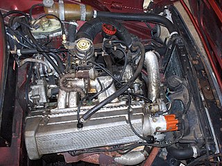
Vapourising oil engine
First production oil engine
Akroyd-Stuart's engines were built from 26 June 1891 by Richard Hornsby & Sons in Grantham, a large manufacturer of steam engines and agricultural equipment, as the Hornsby Akroyd Patent Oil Engine under licence and were first sold commercially on 8 July 1892. Other engineering companies had been offered the option of manufacturing the engine, but they saw it as a threat to their business, and so declined the offer.
Adaption to compression ignition
In 1892, T. H. Barton at Hornsbys enhanced the engine by replacing the vaporiser with a new cylinder head and increased the compression ratio tomake the engine run on compression alone pre-dating Rudolph Diesel's engine.[10] ThisHornsby-Akroyd oil engine design was hugely successful: during the period from1891 through1905, atotal of32,417 engines were produced. Theywould provide electricity for lighting the Taj Mahal, theRock of Gibraltar, theStatue of Liberty (chosen after Hornsby won the oil engine prize at the Chicago World's Fair of1893), many lighthouses, andfor powering Guglielmo Marconi's first transatlantic radio broadcast.
The compression ratio is the ratio between the volume of the cylinder and combustion chamber in an internal combustion engine at their maximum and minimum values.
The diesel engine, named after Rudolf Diesel, is an internal combustion engine in which ignition of the fuel is caused by the elevated temperature of the air in the cylinder due to mechanical compression; thus, the diesel engine is called a compression-ignition engine. This contrasts with engines using spark plug-ignition of the air-fuel mixture, such as a petrol engine or a gas engine.
Fuel injection is the introduction of fuel in an internal combustion engine, most commonly automotive engines, by the means of an injector. This article focuses on fuel injection in reciprocating piston and Wankel rotary engines.
In engineering, the Miller cycle is a thermodynamic cycle used in a type of internal combustion engine. The Miller cycle was patented by Ralph Miller, an American engineer, U.S. patent 2,817,322 dated Dec 24, 1957. The engine may be two- or four-stroke and may be run on diesel fuel, gases, or dual fuel. It uses a supercharger or a turbocharger to offset the performance loss of the Atkinson cycle.
A two-strokeengine is a type of internal combustion engine that completes a power cycle with two strokes of the piston in one revolution of the crankshaft. A four-stroke engine requires four strokes of the piston to complete a power cycle in two crankshaft revolutions. In a two-stroke engine, the end of the combustion stroke and the beginning of the compression stroke happen simultaneously, with the intake and exhaust functions occurring at the same time.
In internal combustion engines, exhaust gas recirculation (EGR) is a nitrogen oxide (NOx) emissions reduction technique used in petrol/gasoline, diesel engines and some hydrogen engines. EGR works by recirculating a portion of an engine's exhaust gas back to the engine cylinders. The exhaust gas displaces atmospheric air and reduces O2 in the combustion chamber. Reducing the amount of oxygen reduces the amount of fuel that can burn in the cylinder thereby reducing peak in-cylinder temperatures. The actual amount of recirculated exhaust gas varies with the engine operating parameters.
A four-strokeengine is an internal combustion (IC) engine in which the piston completes four separate strokes while turning the crankshaft. A stroke refers to the full travel of the piston along the cylinder, in either direction. The four separate strokes are termed:
Intake: Also known as induction or suction. This stroke of the piston begins at top dead center (T.D.C.) and ends at bottom dead center (B.D.C.). In this stroke the intake valve must be in the open position while the piston pulls an air-fuel mixture into the cylinder by producing a partial vacuum in the cylinder through its downward motion.
Compression: This stroke begins at B.D.C, or just at the end of the suction stroke, and ends at T.D.C. In this stroke the piston compresses the air-fuel mixture in preparation for ignition during the power stroke (below). Both the intake and exhaust valves are closed during this stage.
Combustion: Also known as power or ignition. This is the start of the second revolution of the four stroke cycle. At this point the crankshaft has completed a full 360 degree revolution. While the piston is at T.D.C. the compressed air-fuel mixture is ignited by a spark plug or by heat generated by high compression, forcefully returning the piston to B.D.C. This stroke produces mechanical work from the engine to turn the crankshaft.
Exhaust: Also known as outlet. During the exhaust stroke, the piston, once again, returns from B.D.C. to T.D.C. while the exhaust valve is open. This action expels the spent air-fuel mixture through the exhaust port.
A hot-tube ignitor was an early device that fit onto the cylinder head of an internal-combustion engine, used to ignite the compressed fuel/air mixture by means of a flame heating part of the tube red-hot. A hot-tube ignitor consisted of a metal or porcelain tube, closed at one end and attached to the cylinder head at the other and an adjustable burner that could be moved to position its flame at any point along the length of the tube.
In spark-ignition internal combustion engines, knocking occurs when combustion of some of the air/fuel mixture in the cylinder does not result from propagation of the flame front ignited by the spark plug, but when one or more pockets of air/fuel mixture explode outside the envelope of the normal combustion front. The fuel–air charge is meant to be ignited by the spark plug only, and at a precise point in the piston's stroke. Knock occurs when the peak of the combustion process no longer occurs at the optimum moment for the four-stroke cycle. The shock wave creates the characteristic metallic "pinging" sound, and cylinder pressure increases dramatically. Effects of engine knocking range from inconsequential to completely destructive.
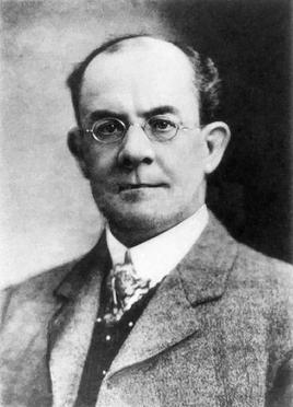
Herbert Akroyd-Stuart was an English inventor who is noted for his invention of the hot bulb engine, or heavy oil engine.
Homogeneous Charge Compression Ignition (HCCI) is a form of internal combustion in which well-mixed fuel and oxidizer are compressed to the point of auto-ignition. As in other forms of combustion, this exothermic reaction produces heat that can be transformed into work in a heat engine.
In the context of an internal combustion engine, the term stroke has the following related meanings:
The Bourke engine was an attempt by Russell Bourke, in the 1920s, to improve the two-stroke internal combustion engine. Despite finishing his design and building several working engines, the onset of World War II, lack of test results, and the poor health of his wife compounded to prevent his engine from ever coming successfully to market. The main claimed virtues of the design are that it has only two moving parts, is lightweight, has two power pulses per revolution, and does not need oil mixed into the fuel.
George Bailey Brayton (1830–1892) was an American mechanical engineer and inventor. He was noted for introducing the constant pressure engine that is the basis for the gas turbine, and which is now referred to as the Brayton cycle.
The hot-bulb engine, also known as a semi-diesel, is a type of internal combustion engine in which fuel ignites by coming in contact with a red-hot metal surface inside a bulb, followed by the introduction of air (oxygen) compressed into the hot-bulb chamber by the rising piston. There is some ignition when the fuel is introduced, but it quickly uses up the available oxygen in the bulb. Vigorous ignition takes place only when sufficient oxygen is supplied to the hot-bulb chamber on the compression stroke of the engine.
The term six-stroke engine has been applied to a number of alternative internal combustion engine designs that attempt to improve on traditional two-stroke and four-stroke engines. Claimed advantages may include increased fuel efficiency, reduced mechanical complexity, and/or reduced emissions. These engines can be divided into two groups based on the number of pistons that contribute to the six strokes.
Diesel engine runaway is an occurrence in diesel engines, in which the engine draws extra fuel from an unintended source and overspeeds at higher and higher RPM, producing up to ten times the engine's rated output until destroyed by mechanical failure or bearing seizure due to a lack of lubrication. Hot-bulb engines and jet engines can also run away via the same process.
Internal combustion engines date back to between the 10th and 13th centuries, when the first rocket engines were invented in China. Following the first commercial steam engine by Thomas Savery in 1698, various efforts were made during the 18th century to develop equivalent internal combustion engines. In 1791, the English inventor John Barber patented a gas turbine. In 1794, Thomas Mead patented a gas engine. Also in 1794, Robert Street patented an internal-combustion engine, which was also the first to use liquid fuel (petroleum) and built an engine around that time. In 1798, John Stevens designed the first American internal combustion engine. In 1807, French engineers Nicéphore and Claude Niépce ran a prototype internal combustion engine, using controlled dust explosions, the Pyréolophore. This engine powered a boat on the river in France. The same year, the Swiss engineer François Isaac de Rivaz built and patented a hydrogen and oxygen-powered internal-combustion engine. Fitted to a crude four-wheeled wagon, François Isaac de Rivaz first drove it 100 metres in 1813, thus making history as the first car-like vehicle known to have been powered by an internal-combustion engine.
The Hesselman engine is a hybrid between a petrol engine and a diesel engine. It was designed and introduced in 1925 by Swedish engineer Jonas Hesselman.
An internal combustion engine is a heat engine in which the combustion of a fuel occurs with an oxidizer in a combustion chamber that is an integral part of the working fluid flow circuit. In an internal combustion engine, the expansion of the high-temperature and high-pressure gases produced by combustion applies direct force to some component of the engine. The force is typically applied to pistons, turbine blades, a rotor, or a nozzle. This force moves the component over a distance, transforming chemical energy into kinetic energy which is used to propel, move or power whatever the engine is attached to.
This page is based on this Wikipedia article Text is available under the CC BY-SA 4.0 license; additional terms may apply. Images, videos and audio are available under their respective licenses.