This article's lead sectionmay be too short to adequately summarize the key points. Please consider expanding the lead to provide an accessible overview of all important aspects of the article.(January 2019)
Impedance is an important parameter used to characterize electronic components, electronic circuits, and the materials used to make components. Impedance analysis can also be used to characterize materials exhibiting dielectric behavior such as biological tissue, foodstuffs or geological samples.
Impedance analyzers come in three distinct hardware implementations, and together these three implementations can probe from ultra low frequency to ultra high frequency and can measure impedances from μΩ to TΩ.
Operation
Impedance analyzers are a class of instruments which measure complex electrical impedance as a function of frequency. This involves the phase sensitive measurement of current and voltage applied to a device under test while the measurement frequency is varied over the course of the measurement. Key specifications of an impedance analyzer are the frequency range, impedance range, absolute impedance accuracy and phase angle accuracy. Further specifications include the ability to apply voltage bias and current bias while measuring, and the measurement speed[1].
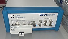
Computer controlled impedance analyzer based on the direct I-V mode with test fixture attached.
Impedance analyzers typically offer highly accurate impedance measurements, e.g. with a basic accuracy of up to 0.05%,[2] and a frequency measurement range from μHz to GHz. Impedance values can range over many decades from μΩ to TΩ, whereas the phase angle accuracy is in the range of 10 millidegree. Measured impedance values include absolute impedance, the real and imaginary part of the measured impedance and the phase between the voltage and current. Model-derived impedance parameters such as conductance, inductance and capacitance are calculated based on a replacement circuit model and subsequently displayed.
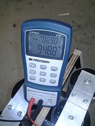
LCR meters also provide impedance measurement functionality, typically with similar accuracy but lower frequency range. The measurement frequency of LCR meters is generally fixed rather than swept, and cannot be displayed graphically.
Impedance analyzers have three distinct hardware implementations:
A fourth implementation, the vector network analyzer (VNA), can be considered a distinct instrument. In contrast to impedance analyzers, VNAs also measure impedance but usually at much higher frequencies and with much lower accuracy compared to impedance analyzers.[4]
Reactance chart
Most impedance analyzers come with a reactance chart[5] which shows the reactance values for capacitive reactance XC and inductive reactance XL for a given frequency. The accuracy of the instrument is transposed on the chart to allow the user to quickly see what accuracy they can expect for a given frequency and reactance.
↑ Masahiro Horibe (2017) Performance comparisons between impedance analyzers and vector network analyzers for impedance measurement below 100 MHz frequency, 89th ARFTG Microwave Measurement Conference
↑ Harold A. Wheeler (1950) Reactance Chart, Proceedings of the I.R.E., p. 1392-1397
Related Research Articles
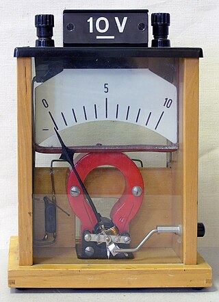
A voltmeter is an instrument used for measuring electric potential difference between two points in an electric circuit. It is connected in parallel. It usually has a high resistance so that it takes negligible current from the circuit.
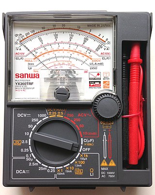
A multimeter is a measuring instrument that can measure multiple electrical properties. A typical multimeter can measure voltage, resistance, and current, in which case can be used as a voltmeter, ohmmeter, and ammeter. Some feature the measurement of additional properties such as temperature and capacitance.
In radio engineering and telecommunications, standing wave ratio (SWR) is a measure of impedance matching of loads to the characteristic impedance of a transmission line or waveguide. Impedance mismatches result in standing waves along the transmission line, and SWR is defined as the ratio of the partial standing wave's amplitude at an antinode (maximum) to the amplitude at a node (minimum) along the line.
In electrical engineering, impedance is the opposition to alternating current presented by the combined effect of resistance and reactance in a circuit.
Electronic test equipment is used to create signals and capture responses from electronic devices under test (DUTs). In this way, the proper operation of the DUT can be proven or faults in the device can be traced. Use of electronic test equipment is essential to any serious work on electronics systems.
In electronics, a voltage divider (also known as a potential divider) is a passive linear circuit that produces an output voltage (Vout) that is a fraction of its input voltage (Vin). Voltage division is the result of distributing the input voltage among the components of the divider. A simple example of a voltage divider is two resistors connected in series, with the input voltage applied across the resistor pair and the output voltage emerging from the connection between them.
An antenna tuner is a passive electronic device inserted between a radio transmitter and its antenna. Its purpose is to optimize power transfer by matching the impedance of the radio to the signal impedance on the feedline to the antenna.
An antenna analyzer or in British aerial analyser is a device used for measuring the input impedance of antenna systems in radio electronics applications.
A current transformer (CT) is a type of transformer that is used to reduce or multiply an alternating current (AC). It produces a current in its secondary which is proportional to the current in its primary.
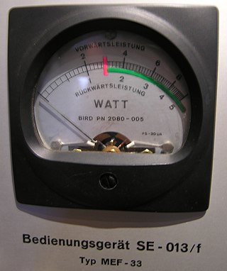
The wattmeter is an instrument for measuring the electric active power in watts of any given circuit. Electromagnetic wattmeters are used for measurement of utility frequency and audio frequency power; other types are required for radio frequency measurements.
A network analyzer is an instrument that measures the network parameters of electrical networks. Today, network analyzers commonly measure s–parameters because reflection and transmission of electrical networks are easy to measure at high frequencies, but there are other network parameter sets such as y-parameters, z-parameters, and h-parameters. Network analyzers are often used to characterize two-port networks such as amplifiers and filters, but they can be used on networks with an arbitrary number of ports.
Bioelectrical impedance analysis (BIA) is a method for estimating body composition, in particular body fat and muscle mass, where a weak electric current flows through the body and the voltage is measured in order to calculate impedance of the body. Most body water is stored in muscle. Therefore, if a person is more muscular there is a high chance that the person will also have more body water, which leads to lower impedance. Since the advent of the first commercially available devices in the mid-1980s the method has become popular owing to its ease of use and portability of the equipment. It is familiar in the consumer market as a simple instrument for estimating body fat. BIA actually determines the electrical impedance, or opposition to the flow of an electric current through body tissues which can then be used to estimate total body water (TBW), which can be used to estimate fat-free body mass and, by difference with body weight, body fat.
A test probe is a physical device used to connect electronic test equipment to a device under test (DUT). Test probes range from very simple, robust devices to complex probes that are sophisticated, expensive, and fragile. Specific types include test prods, oscilloscope probes and current probes. A test probe is often supplied as a test lead, which includes the probe, cable and terminating connector.
In electrical engineering, four-terminal sensing, 4-wire sensing, or 4-point probes method is an electrical impedance measuring technique that uses separate pairs of current-carrying and voltage-sensing electrodes to make more accurate measurements than the simpler and more usual two-terminal (2T) sensing. Four-terminal sensing is used in some ohmmeters and impedance analyzers, and in wiring for strain gauges and resistance thermometers. Four-point probes are also used to measure sheet resistance of thin films.
A ceramic capacitor is a fixed-value capacitor where the ceramic material acts as the dielectric. It is constructed of two or more alternating layers of ceramic and a metal layer acting as the electrodes. The composition of the ceramic material defines the electrical behavior and therefore applications. Ceramic capacitors are divided into two application classes:
An oscilloscope is a type of electronic test instrument that graphically displays varying voltages of one or more signals as a function of time. Their main purpose is capturing information on electrical signals for debugging, analysis, or characterization. The displayed waveform can then be analyzed for properties such as amplitude, frequency, rise time, time interval, distortion, and others. Originally, calculation of these values required manually measuring the waveform against the scales built into the screen of the instrument. Modern digital instruments may calculate and display these properties directly.
An LCR meter is a type of electronic test equipment used to measure the inductance (L), capacitance (C), and resistance (R) of an electronic component. In the simpler versions of this instrument the impedance was measured internally and converted for display to the corresponding capacitance or inductance value. Readings should be reasonably accurate if the capacitor or inductor device under test does not have a significant resistive component of impedance. More advanced designs measure true inductance or capacitance, as well as the equivalent series resistance of capacitors and the Q factor of inductive components.
Electrical measurements are the methods, devices and calculations used to measure electrical quantities. Measurement of electrical quantities may be done to measure electrical parameters of a system. Using transducers, physical properties such as temperature, pressure, flow, force, and many others can be converted into electrical signals, which can then be conveniently measured and recorded. High-precision laboratory measurements of electrical quantities are used in experiments to determine fundamental physical properties such as the charge of the electron or the speed of light, and in the definition of the units for electrical measurements, with precision in some cases on the order of a few parts per million. Less precise measurements are required every day in industrial practice. Electrical measurements are a branch of the science of metrology.
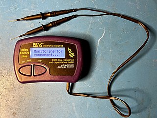
An ESR meter is a two-terminal electronic measuring instrument designed and used primarily to measure the equivalent series resistance (ESR) of real capacitors; usually without the need to disconnect the capacitor from the circuit it is connected to. Other types of meters used for routine servicing, including normal capacitance meters, cannot be used to measure a capacitor's ESR, although combined meters are available that measure both ESR and out-of-circuit capacitance. A standard (DC) milliohmmeter or multimeter cannot be used to measure ESR, because a steady direct current cannot be passed through the capacitor. Most ESR meters can also be used to measure non-inductive low-value resistances, whether or not associated with a capacitor; this leads to several additional applications described below.
The transformer ratio arm bridge or TRA bridge is a type of bridge circuit for measuring electronic components, using a.c. It can be designed to work in terms of either impedance or admittance. It can be used on resistors, capacitors and inductors, measuring minor as well as major terms, e.g. series resistance in capacitors. It is probably the most accurate type of bridge available, being capable of the precision needed, for example, when checking secondary component standards against national standards.
This page is based on this Wikipedia article Text is available under the CC BY-SA 4.0 license; additional terms may apply. Images, videos and audio are available under their respective licenses.