
The characteristic impedance or surge impedance (usually written Z0) of a uniform transmission line is the ratio of the amplitudes of voltage and current of a single wave propagating along the line; that is, a wave travelling in one direction in the absence of reflections in the other direction. Alternatively, and equivalently, it can be defined as the input impedance of a transmission line when its length is infinite. Characteristic impedance is determined by the geometry and materials of the transmission line and, for a uniform line, is not dependent on its length. The SI unit of characteristic impedance is the ohm.

In electrical engineering, the input impedance of an electrical network is the measure of the opposition to current (impedance), both static (resistance) and dynamic (reactance), into a load network that is external to the electrical source network. The input admittance is a measure of the load network's propensity to draw current. The source network is the portion of the network that transmits power, and the load network is the portion of the network that consumes power.
In electrical engineering and electronics, a network is a collection of interconnected components. Network analysis is the process of finding the voltages across, and the currents through, all network components. There are many techniques for calculating these values; however, for the most part, the techniques assume linear components. Except where stated, the methods described in this article are applicable only to linear network analysis.
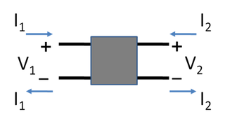
In electronics, a two-port network is an electrical network or device with two pairs of terminals to connect to external circuits. Two terminals constitute a port if the currents applied to them satisfy the essential requirement known as the port condition: the current entering one terminal must equal the current emerging from the other terminal on the same port. The ports constitute interfaces where the network connects to other networks, the points where signals are applied or outputs are taken. In a two-port network, often port 1 is considered the input port and port 2 is considered the output port.
Scattering parameters or S-parameters describe the electrical behavior of linear electrical networks when undergoing various steady state stimuli by electrical signals.
Foster's reactance theorem is an important theorem in the fields of electrical network analysis and synthesis. The theorem states that the reactance of a passive, lossless two-terminal (one-port) network always strictly monotonically increases with frequency. It is easily seen that the reactances of inductors and capacitors individually increase with frequency and from that basis a proof for passive lossless networks generally can be constructed. The proof of the theorem was presented by Ronald Martin Foster in 1924, although the principle had been published earlier by Foster's colleagues at American Telephone & Telegraph.

An attenuator is an electronic device that reduces the power of a signal without appreciably distorting its waveform.

Zobel networks are a type of filter section based on the image-impedance design principle. They are named after Otto Zobel of Bell Labs, who published a much-referenced paper on image filters in 1923. The distinguishing feature of Zobel networks is that the input impedance is fixed in the design independently of the transfer function. This characteristic is achieved at the expense of a much higher component count compared to other types of filter sections. The impedance would normally be specified to be constant and purely resistive. For this reason, Zobel networks are also known as constant resistance networks. However, any impedance achievable with discrete components is possible.
In electrical engineering, the power gain of an electrical network is the ratio of an output power to an input power. Unlike other signal gains, such as voltage and current gain, "power gain" may be ambiguous as the meaning of terms "input power" and "output power" is not always clear. Three important power gains are operating power gain, transducer power gain and available power gain. Note that all these definitions of power gains employ the use of average power quantities and therefore the term "average" is often suppressed, which can be confusing at occasions.

The Π pad is a specific type of attenuator circuit in electronics whereby the topology of the circuit is formed in the shape of the Greek capital letter pi (Π).
Image impedance is a concept used in electronic network design and analysis and most especially in filter design. The term image impedance applies to the impedance seen looking into a port of a network. Usually a two-port network is implied but the concept can be extended to networks with more than two ports. The definition of image impedance for a two-port network is the impedance, Zi 1, seen looking into port 1 when port 2 is terminated with the image impedance, Zi 2, for port 2. In general, the image impedances of ports 1 and 2 will not be equal unless the network is symmetrical with respect to the ports.
Constant k filters, also k-type filters, are a type of electronic filter designed using the image method. They are the original and simplest filters produced by this methodology and consist of a ladder network of identical sections of passive components. Historically, they are the first filters that could approach the ideal filter frequency response to within any prescribed limit with the addition of a sufficient number of sections. However, they are rarely considered for a modern design, the principles behind them having been superseded by other methodologies which are more accurate in their prediction of filter response.
m-derived filters or m-type filters are a type of electronic filter designed using the image method. They were invented by Otto Zobel in the early 1920s. This filter type was originally intended for use with telephone multiplexing and was an improvement on the existing constant k type filter. The main problem being addressed was the need to achieve a better match of the filter into the terminating impedances. In general, all filters designed by the image method fail to give an exact match, but the m-type filter is a big improvement with suitable choice of the parameter m. The m-type filter section has a further advantage in that there is a rapid transition from the cut-off frequency of the passband to a pole of attenuation just inside the stopband. Despite these advantages, there is a drawback with m-type filters; at frequencies past the pole of attenuation, the response starts to rise again, and m-types have poor stopband rejection. For this reason, filters designed using m-type sections are often designed as composite filters with a mixture of k-type and m-type sections and different values of m at different points to get the optimum performance from both types.
mm'-type filters, also called double-m-derived filters, are a type of electronic filter designed using the image method. They were patented by Otto Zobel in 1932. Like the m-type filter from which it is derived, the mm'-type filter type was intended to provide an improved impedance match into the filter termination impedances and originally arose in connection with telephone frequency division multiplexing. The filter has a similar transfer function to the m-type, having the same advantage of rapid cut-off, but the input impedance remains much more nearly constant if suitable parameters are chosen. In fact, the cut-off performance is better for the mm'-type if like-for-like impedance matching are compared rather than like-for-like transfer function. It also has the same drawback of a rising response in the stopband as the m-type. However, its main disadvantage is its much increased complexity which is the chief reason its use never became widespread. It was only ever intended to be used as the end sections of composite filters, the rest of the filter being made up of other sections such as k-type and m-type sections.
A quarter-wave impedance transformer, often written as λ/4 impedance transformer, is a transmission line or waveguide used in electrical engineering of length one-quarter wavelength (λ), terminated with some known impedance. It presents at its input the dual of the impedance with which it is terminated.
An equivalent impedance is an equivalent circuit of an electrical network of impedance elements which presents the same impedance between all pairs of terminals as did the given network. This article describes mathematical transformations between some passive, linear impedance networks commonly found in electronic circuits.

The T pad is a specific type of attenuator circuit in electronics whereby the topology of the circuit is formed in the shape of the letter "T".
The mobility analogy, also called admittance analogy or Firestone analogy, is a method of representing a mechanical system by an analogous electrical system. The advantage of doing this is that there is a large body of theory and analysis techniques concerning complex electrical systems, especially in the field of filters. By converting to an electrical representation, these tools in the electrical domain can be directly applied to a mechanical system without modification. A further advantage occurs in electromechanical systems: Converting the mechanical part of such a system into the electrical domain allows the entire system to be analysed as a unified whole.
Network synthesis is a design technique for linear electrical circuits. Synthesis starts from a prescribed impedance function of frequency or frequency response and then determines the possible networks that will produce the required response. The technique is to be compared to network analysis in which the response of a given circuit is calculated. Prior to network synthesis, only network analysis was available, but this requires that one already knows what form of circuit is to be analysed. There is no guarantee that the chosen circuit will be the closest possible match to the desired response, nor that the circuit is the simplest possible. Network synthesis directly addresses both these issues. Network synthesis has historically been concerned with synthesising passive networks, but is not limited to such circuits.
Performance modelling is the abstraction of a real system into a simplified representation to enable the prediction of performance. The creation of a model can provide insight into how a proposed or actual system will or does work. This can, however, point towards different things to people belonging to different fields of work.


