
An operational amplifier is a DC-coupled high-gain electronic voltage amplifier with a differential input and, usually, a single-ended output. In this configuration, an op amp produces an output potential that is typically 100,000 times larger than the potential difference between its input terminals. Operational amplifiers had their origins in analog computers, where they were used to perform mathematical operations in linear, non-linear, and frequency-dependent circuits.

In electronics, a comparator is a device that compares two voltages or currents and outputs a digital signal indicating which is larger. It has two analog input terminals and and one binary digital output . The output is ideally
Transistor–transistor logic (TTL) is a logic family built from bipolar junction transistors. Its name signifies that transistors perform both the logic function and the amplifying function, as opposed to resistor–transistor logic (RTL) or diode–transistor logic (DTL).

In electronics, a multi-transistor configuration called the Darlington configuration is a circuit consisting of two bipolar transistors with the emitter of one transistor connected to the base of the other, such that the current amplified by the first transistor is amplified further by the second one. The collectors of both transistors are connected together. This configuration has a much higher current gain than each transistor taken separately. It acts like and is often packaged as a single transistor. It was invented in 1953 by Sidney Darlington.

In electronics a relaxation oscillator is a nonlinear electronic oscillator circuit that produces a nonsinusoidal repetitive output signal, such as a triangle wave or square wave. The circuit consists of a feedback loop containing a switching device such as a transistor, comparator, relay, op amp, or a negative resistance device like a tunnel diode, that repetitively charges a capacitor or inductor through a resistance until it reaches a threshold level, then discharges it again. The period of the oscillator depends on the time constant of the capacitor or inductor circuit. The active device switches abruptly between charging and discharging modes, and thus produces a discontinuously changing repetitive waveform. This contrasts with the other type of electronic oscillator, the harmonic or linear oscillator, which uses an amplifier with feedback to excite resonant oscillations in a resonator, producing a sine wave. Relaxation oscillators are used to produce low frequency signals for applications such as blinking lights and electronic beepers and in voltage controlled oscillators (VCOs), inverters and switching power supplies, dual-slope analog to digital converters, and function generators.
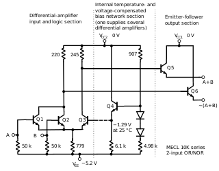
In electronics, emitter-coupled logic (ECL) is a high-speed integrated circuit bipolar transistor logic family. ECL uses an overdriven bipolar junction transistor (BJT) differential amplifier with single-ended input and limited emitter current to avoid the saturated region of operation and its slow turn-off behavior. As the current is steered between two legs of an emitter-coupled pair, ECL is sometimes called current-steering logic (CSL), current-mode logic (CML) or current-switch emitter-follower (CSEF) logic.
In electronics, a linear regulator is a system used to maintain a steady voltage. The resistance of the regulator varies in accordance with both the input voltage and the load, resulting in a constant voltage output. The regulating device is made to act like a variable resistor, continuously adjusting a voltage divider network to maintain a constant output voltage and continually dissipating the difference between the input and regulated voltages as waste heat. By contrast, a switching regulator uses an active device that switches on and off to maintain an average value of output. Because the regulated voltage of a linear regulator must always be lower than input voltage, efficiency is limited and the input voltage must be high enough to always allow the active device to drop some voltage.

In electronics, a Schmitt trigger is a comparator circuit with hysteresis implemented by applying positive feedback to the noninverting input of a comparator or differential amplifier. It is an active circuit which converts an analog input signal to a digital output signal. The circuit is named a trigger because the output retains its value until the input changes sufficiently to trigger a change. In the non-inverting configuration, when the input is higher than a chosen threshold, the output is high. When the input is below a different (lower) chosen threshold the output is low, and when the input is between the two levels the output retains its value. This dual threshold action is called hysteresis and implies that the Schmitt trigger possesses memory and can act as a bistable multivibrator. There is a close relation between the two kinds of circuits: a Schmitt trigger can be converted into a latch and a latch can be converted into a Schmitt trigger.

The 555 timer IC is an integrated circuit (chip) used in a variety of timer, delay, pulse generation, and oscillator applications. Derivatives provide two (556) or four (558) timing circuits in one package. It was commercialized in 1972 by Signetics. Numerous companies have made the original bipolar timers and similar low-power CMOS timers too. In 2017, it was said over a billion 555 timers are produced annually by some estimates, and "probably the most popular integrated circuit ever made."

An electronic component is any basic discrete device or physical entity in an electronic system used to affect electrons or their associated fields. Electronic components are mostly industrial products, available in a singular form and are not to be confused with electrical elements, which are conceptual abstractions representing idealized electronic components and elements.

The MK484 AM radio IC is a fully functional AM radio detector on a chip. It is constructed in a TO-92 case, resembling a small transistor. It replaces the similar ZN414 AM radio IC from the 1970s. The MK484 is favored by many hobbyists. It is advantageous in that it performs well with minimal discrete components, and can run from a single 1.5-volt cell.

Robert John Widlar was an American electronics engineer and a designer of linear integrated circuits (ICs).

The LM317 is a popular adjustable positive linear voltage regulator. It was designed by Bob Dobkin in 1976 while he worked at National Semiconductor.

In electronics, an LED circuit or LED driver is an electrical circuit used to power a light-emitting diode (LED). The circuit must provide sufficient current to light the LED at the required brightness, but must limit the current to prevent damaging the LED. The voltage drop across an LED is approximately constant over a wide range of operating current; therefore, a small increase in applied voltage greatly increases the current. Very simple circuits are used for low-power indicator LEDs. More complex, current source circuits are required when driving high-power LEDs for illumination to achieve correct current regulation.

78xx is a family of self-contained fixed linear voltage regulator integrated circuits. The 78xx family is commonly used in electronic circuits requiring a regulated power supply due to their ease-of-use and low cost.

The LM386 is an integrated circuit containing a low-voltage audio power amplifier. It is suitable for battery-powered devices such as radios, guitar amplifiers, and hobby electronics projects. The IC consists of an 8-pin dual in-line package (DIP-8) and can output 0.25 to 1 watts of power, depending on the model, using a 9-volt power supply.
LTspice is a SPICE-based analog electronic circuit simulator computer software, produced by semiconductor manufacturer Analog Devices. It is the most widely distributed and used SPICE software in the industry. Though it is freeware, LTspice is not artificially restricted to limit its capabilities.
A voltage-controlled resistor (VCR) is a three-terminal active device with one input port and two output ports. The input-port voltage controls the value of the resistor between the output ports. VCRs are most often built with field-effect transistors (FETs). Two types of FETs are often used: the JFET and the MOSFET. There are both floating voltage-controlled resistors and grounded voltage-controlled resistors. Floating VCRs can be placed between two passive or active components. Grounded VCRs, the more common and less complicated design, require that one port of the voltage-controlled resistor be grounded.

The TL431 is a three-terminal adjustable precision shunt voltage regulator integrated circuit. With the use of an external voltage divider, a TL431 can regulate voltages ranging from 2.5 to 36 V, at currents up 100 mA. The typical initial deviation of reference voltage from the nominal 2.495 V level is measured in millivolts, the maximum worst-case deviation is measured in tens of millivolts. The circuit can control power transistors directly; combinations of the TL431 with power MOS transistors are used in high efficiency, very low dropout linear regulators. The TL431 is the de facto industry standard error amplifier circuit for switched-mode power supplies with optoelectronic coupling of the input and output networks.

