Leavitt-Riedler Pumping Engine

Last updated
Leavitt-Riedler Pumping Engine Leavitt-Riedler Pumping Engine.JPG
Leavitt-Riedler Pumping Engine

The Leavitt-Riedler Pumping Engine (1894) is a historic steam engine located in the former Chestnut Hill High Service Pumping Station, in Boston, Massachusetts. It has been declared a historic mechanical engineering landmark by the American Society of Mechanical Engineers. [1] The pumping station was decommissioned in the 1970s, and turned into the Metropolitan Waterworks Museum in 2011.

Contents

The engine drew steam from a coal-fired boiler, and had a pump valve mechanism which allowed its high-speed operation at a hydraulic head of 128 feet (39 m).

The engine was designed by engineer Erasmus Darwin Leavitt, Jr., of Cambridge, Massachusetts, with a pump valve invented by Prof. Alois Riedler of the Royal Technical College of Charlottenburg (now the Technical University of Berlin) in Berlin, Germany. It was built by N. F. Palmer Jr. & Co. and the Quintard Iron Works, in New York.

In 1894, it was installed as Engine No. 3 of the Chestnut Hill High Station, later named the Boston Water Works. At its normal speed of 50 revolutions per minute, it pumped 25 million gallons of water in 24 hours. According to Carol Poh Miller, when first brought into operation, the engine attracted national attention as "the most efficient pumping engine in the world". [2]

The engine was taken out of service in 1928 but remains in its original location and it is open for public viewing as an exhibit in the Metropolitan Waterworks Museum.

Components and operation

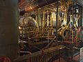
The engine itself is of an unusual triple-expansion, three-crank rocker design, with pistons 13.7, 24.375, and 39 inches (348.0, 619.1, and 990.6 mm) in diameter and 6-foot (1.8 m) stroke. Each rocker is connected both to a crankshaft with a 15-foot (4.6 m) flywheel and to a double acting pump's plunger.

The triple-expansion steam engine cylinders, located on the second story of the engine, are supported by six vertical and six diagonal columns, creating space for three vertical pistons to move up and down. The vertical rods with 6-foot (1.8 m) stroke from the engine drive a horizontal crankshaft which is also connected to a flywheel. Each of the vertical rods is also connected to the back end of a rocking crank, similar to a bellcrank. With the pivot point of the crank in the front side, the up and down motion of the vertical rod on the back end of the crank creates a motion that pulls and pushes the crank backward and forward. There are also three horizontal rods that connect between the horizontal shaft and the cranks. As the shaft turns, the rods move backward and forward nearly horizontally, adding force to the backward and forward motion of the cranks.

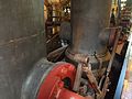
On the front end of the cranks, there are 30-degree inclined rods that are connected to the inclined plungers of the pump proper. The unusual diagonal plungers were created in part by the limitation of the existing engine room. The crank configuration is set in a way that the 6-foot (1.8 m) stroke is reduced to 4-foot (1.2 m) stroke for the inclined rods. Each plunger pumps water in two pump chambers with total of six chambers for the pumping engine. With the reduction of the strokes and the relation of diameters, a higher capacity for pressure can be achieved. The efficiency of the engine also comes from the design of the pump valves by Prof. Riedler. The pump valves which are connected rings that can move up and down to open can close the valves. The pump valve mechanism is controlled by a diagonal rod, powered from a 12-foot (3.7 m) stroke horizontal rod which is connected the crank. The valve rods only close the valves on the reverse stroke and leave the valves free to open automatically to increase the speed of the operation. [3] [4]

See also

Related Research Articles

<span class="mw-page-title-main">Reciprocating engine</span> Engine utilising one or more reciprocating pistons

A reciprocating engine, also often known as a piston engine, is typically a heat engine that uses one or more reciprocating pistons to convert high temperature and high pressure into a rotating motion. This article describes the common features of all types. The main types are: the internal combustion engine, used extensively in motor vehicles; the steam engine, the mainstay of the Industrial Revolution; and the Stirling engine for niche applications. Internal combustion engines are further classified in two ways: either a spark-ignition (SI) engine, where the spark plug initiates the combustion; or a compression-ignition (CI) engine, where the air within the cylinder is compressed, thus heating it, so that the heated air ignites fuel that is injected then or earlier.

<span class="mw-page-title-main">Newcomen atmospheric engine</span> Early engine invented by Thomas Newcomen.

The atmospheric engine was invented by Thomas Newcomen in 1712, and is often referred to as the Newcomen fire engine or simply as a Newcomen engine. The engine was operated by condensing steam drawn into the cylinder, thereby creating a partial vacuum which allowed the atmospheric pressure to push the piston into the cylinder. It was historically significant as the first practical device to harness steam to produce mechanical work. Newcomen engines were used throughout Britain and Europe, principally to pump water out of mines. Hundreds were constructed throughout the 18th century.

<span class="mw-page-title-main">Crosshead</span> Sliding pin joint in a slider-crank linkage, commonly used in engine pistons

In mechanical engineering, a crosshead is a mechanical joint used as part of the slider-crank linkages of long reciprocating engines and reciprocating compressors to eliminate sideways force on the piston. Also, the crosshead enables the connecting rod to freely move outside the cylinder. Because of the very small bore-to-stroke ratio on such engines, the connecting rod would hit the cylinder walls and block the engine from rotating if the piston was attached directly to the connecting rod like on trunk engines. Therefore, the longitudinal dimension of the crosshead must be matched to the stroke of the engine.

<span class="mw-page-title-main">Pumpjack</span> Drive for a reciprocating piston pump in an oil well

A pumpjack is the overground drive for a reciprocating piston pump in an oil well.

<span class="mw-page-title-main">Walschaerts valve gear</span> Type of valve gear

The Walschaerts valve gear is a type of valve gear used to regulate the flow of steam to the pistons in steam locomotives, invented by Belgian railway engineer Egide Walschaerts in 1844. The gear is sometimes named without the final "s", since it was incorrectly patented under that name. It was extensively used in steam locomotives from the late 19th century until the end of the steam era.

<span class="mw-page-title-main">Beam engine</span> Early configuration of the steam engine utilising a rocking beam to connect major components.

A beam engine is a type of steam engine where a pivoted overhead beam is used to apply the force from a vertical piston to a vertical connecting rod. This configuration, with the engine directly driving a pump, was first used by Thomas Newcomen around 1705 to remove water from mines in Cornwall. The efficiency of the engines was improved by engineers including James Watt, who added a separate condenser; Jonathan Hornblower and Arthur Woolf, who compounded the cylinders; and William McNaught, who devised a method of compounding an existing engine. Beam engines were first used to pump water out of mines or into canals but could be used to pump water to supplement the flow for a waterwheel powering a mill.

<span class="mw-page-title-main">Corliss steam engine</span> Type of steam engine using rotary steam valves

A Corliss steam engine is a steam engine, fitted with rotary valves and with variable valve timing patented in 1849, invented by and named after the US engineer George Henry Corliss of Providence, Rhode Island.

<span class="mw-page-title-main">Man engine</span> Vertical transport system used in mines

A man engine is a mechanism of reciprocating ladders and stationary platforms installed in mines to assist the miners' journeys to and from the working levels. It was invented in Germany in the 19th century and was a prominent feature of tin and copper mines in Cornwall until the beginning of the twentieth century.

Artificial lift refers to the use of artificial means to increase the flow of liquids, such as crude oil or water, from a production well. Generally this is achieved by the use of a mechanical device inside the well or by decreasing the weight of the hydrostatic column by injecting gas into the liquid some distance down the well. A newer method called Continuous Belt Transportation (CBT) uses an oil absorbing belt to extract from marginal and idle wells. Artificial lift is needed in wells when there is insufficient pressure in the reservoir to lift the produced fluids to the surface, but often used in naturally flowing wells to increase the flow rate above what would flow naturally. The produced fluid can be oil, water or a mix of oil and water, typically mixed with some amount of gas.

<span class="mw-page-title-main">Arlington Pumping Station</span> United States historic place

The Arlington Pumping Station, built in 1907, is a historic water pumping station on Brattle Court in Arlington, Massachusetts. Its purpose was to provide water to Lexington and higher elevations in Arlington. The station was put in service on December 4, 1907.

<span class="mw-page-title-main">Marine steam engine</span> Steam engine that is used to power a ship or boat

A marine steam engine is a steam engine that is used to power a ship or boat. This article deals mainly with marine steam engines of the reciprocating type, which were in use from the inception of the steamboat in the early 19th century to their last years of large-scale manufacture during World War II. Reciprocating steam engines were progressively replaced in marine applications during the 20th century by steam turbines and marine diesel engines.

<span class="mw-page-title-main">Blowing engine</span> Device which provides forced air to smelters

A blowing engine is a large stationary steam engine or internal combustion engine directly coupled to air pumping cylinders. They deliver a very large quantity of air at a pressure lower than an air compressor, but greater than a centrifugal fan.

Woolstenhulmes & Rye was a company that manufactured stationary steam engines. It was based in Oldham, Lancashire, England. The company produced large steam-driven engines for textile mills in Oldham and elsewhere.

<span class="mw-page-title-main">Chapin Mine Steam Pump Engine</span> United States historic place

The Chapin Mine Steam Pump Engine, also known as The Cornish Pump, is a steam-driven pump located at the corner of Kent Street and Kimberly Avenue in Iron Mountain, Michigan, USA. It is the largest reciprocating steam-driven engine ever built in the United States. It was listed on the National Register of Historic Places in 1981, and designated a Michigan State Historic Site in 1958.

<span class="mw-page-title-main">Return connecting rod engine</span>

A return connecting rod, return piston rod or double piston rod engine or back-acting engine is a particular layout for a steam engine.

<span class="mw-page-title-main">Cataract (beam engine)</span>

A cataract was a speed governing device used for early single-acting beam engines, particularly atmospheric engines and Cornish engines. It was a kind of water clock.

<span class="mw-page-title-main">Triumph 6/1</span> British motorcycle

The Triumph 6/1 is a motorcycle that was made by Triumph at their Coventry factory from 1934 to 1936. Designed by Val Page, the 6/1 was the first Triumph motorcycle to use a parallel-twin engine. A sidecar-equipped 6/1 won a silver medal in the 1933 International Six Days Trial and went on to win the Maudes Trophy for 1933. The 6/1 was a commercial failure, selling fewer than 600 in two years on the market.

Stuart Turner Ltd is a British engineering company, based in Henley-on-Thames, Oxfordshire, England, founded by engineer Sidney Marmaduke Stuart Turner in 1906.

<span class="mw-page-title-main">Metropolitan Waterworks Museum</span> Museum in Chestnut Hill, Massachusetts

The Waterworks Museum is a museum in the Chestnut Hill Waterworks building, originally a high-service pumping station of the Boston Metropolitan Waterworks. It contains well-preserved mechanical engineering devices in a Richardsonian Romanesque building.

<span class="mw-page-title-main">Cornish engine valve gear</span>

Valve gear opens and closes valves in the correct order. In rotating engines valve timings can be driven by eccentrics or cranks, but in non-rotative beam engines these options are not available. In the Cornish engine valves are driven either manually or through ‘plug rods’ and tappets driven from the beam. This permits the insertions of delays at various points in the cycle, allowing a Cornish Engine to vary from one stroke in ten minutes, to ten or more strokes in one minute, but also leads to some less familiar components when compared with rotative engines.

References

  1. "Leavitt-Riedler Pumping Engine". American Society of Mechanical Engineers. Retrieved 2019-12-01.
  2. "Record Making Pumping Engine, Chestnut Hill Pumping Station, Boston, Mass". Power. 16: 1–6. April 1896.
  3. The Leavitt Pumping Engine at Chestnut Hill Station of the Metropolitan District Commission Boston, Mass (PDF). American Society of Mechanical Engineers. 14 December 1973. Archived from the original (PDF) on 26 September 2007. Retrieved 3 September 2014.
  4. "Animation Series". Cincinnati Triple Steam. Retrieved 3 September 2014.