Linear phase is a property of a filter where the phase response of the filter is a linear function of frequency. The result is that all frequency components of the input signal are shifted in time (usually delayed) by the same constant amount (the slope of the linear function), which is referred to as the group delay. Consequently, there is no phase distortion due to the time delay of frequencies relative to one another.
For discrete-time signals, perfect linear phase is easily achieved with a finite impulse response (FIR) filter by having coefficients which are symmetric or anti-symmetric.[1] Approximations can be achieved with infinite impulse response (IIR) designs, which are more computationally efficient. Several techniques are:
a Bessel transfer function which has a maximally flat group delay approximation function
A filter is called a linear phase filter if the phase component of the frequency response is a linear function of frequency. For a continuous-time application, the frequency response of the filter is the Fourier transform of the filter's impulse response, and a linear phase version has the form:
For approximately linear phase, it is sufficient to have that property only in the passband(s) of the filter, where |A(ω)| has relatively large values. Therefore, both magnitude and phase graphs (Bode plots) are customarily used to examine a filter's linearity. A "linear" phase graph may contain discontinuities of π and/or 2π radians. The smaller ones happen where A(ω) changes sign. Since |A(ω)| cannot be negative, the changes are reflected in the phase plot. The 2π discontinuities happen because of plotting the principal value of instead of the actual value.
In discrete-time applications, one only examines the region of frequencies between 0 and the Nyquist frequency, because of periodicity and symmetry. Depending on the frequency units, the Nyquist frequency may be 0.5, 1.0, π, or ½ of the actual sample-rate. Some examples of linear and non-linear phase are shown below.
Bode plots. Phase discontinuities are π radians, indicating a sign reversal.
Phase discontinuities are removed by allowing negative amplitude.
Two depictions of the frequency response of a simple FIR filter
A discrete-time filter with linear phase may be achieved by an FIR filter which is either symmetric or anti-symmetric.[2] A necessary but not sufficient condition is:
Systems with generalized linear phase have an additional frequency-independent constant added to the phase. In the discrete-time case, for example, the frequency response has the form:
for
Because of this constant, the phase of the system is not a strictly linear function of frequency, but it retains many of the useful properties of linear phase systems.[4]
↑ Oppenheim, Alan V; Ronald W Schafer (1975). Digital Signal Processing (3ed.). Prentice Hall. ISBN0-13-214635-5.
↑ Oppenheim, Alan V; Ronald W Schafer (1975). Digital Signal Processing (1ed.). Prentice Hall. ISBN0-13-214635-5.
Related Research Articles
In classical mechanics, a harmonic oscillator is a system that, when displaced from its equilibrium position, experiences a restoring force F proportional to the displacement x:
In signal processing, group delay and phase delay are delay times experienced by a signal's various frequency components when the signal passes through a system that is linear time-invariant (LTI), such as a microphone, coaxial cable, amplifier, loudspeaker, telecommunications system or ethernet cable. These delays are generally frequency dependent. This means that different frequency components experience different delays, which cause distortion of the signal's waveform as it passes through the system. This distortion can cause problems such as poor fidelity in analog video and analog audio, or a high bit-error rate in a digital bit stream. For a modulation signal, the signal intelligence is carried exclusively in the wave envelope. Group delay therefore operates only with the frequency components derived from the envelope.
Chebyshev filters are analog or digital filters that have a steeper roll-off than Butterworth filters, and have either passband ripple or stopband ripple. Chebyshev filters have the property that they minimize the error between the idealized and the actual filter characteristic over the range of the filter, but with ripples in the passband. This type of filter is named after Pafnuty Chebyshev because its mathematical characteristics are derived from Chebyshev polynomials. Type I Chebyshev filters are usually referred to as "Chebyshev filters", while type II filters are usually called "inverse Chebyshev filters".
In signal processing, a finite impulse response (FIR) filter is a filter whose impulse response is of finite duration, because it settles to zero in finite time. This is in contrast to infinite impulse response (IIR) filters, which may have internal feedback and may continue to respond indefinitely.
In control theory and signal processing, a linear, time-invariant system is said to be minimum-phase if the system and its inverse are causal and stable.
In mathematics and in signal processing, the Hilbert transform is a specific linear operator that takes a function, u(t) of a real variable and produces another function of a real variable H(u)(t). This linear operator is given by convolution with the function . The Hilbert transform has a particularly simple representation in the frequency domain: It imparts a phase shift of ±90° to every frequency component of a function, the sign of the shift depending on the sign of the frequency. The Hilbert transform is important in signal processing, where it is a component of the analytic representation of a real-valued signal u(t). The Hilbert transform was first introduced by David Hilbert in this setting, to solve a special case of the Riemann–Hilbert problem for analytic functions.
In signal processing, a comb filter is a filter implemented by adding a delayed version of a signal to itself, causing constructive and destructive interference. The frequency response of a comb filter consists of a series of regularly spaced notches in between regularly spaced peaks giving the appearance of a comb.
In physics and engineering, a phasor is a complex number representing a sinusoidal function whose amplitude (A), angular frequency (ω), and initial phase (θ) are time-invariant. It is related to a more general concept called analytic representation, which decomposes a sinusoid into the product of a complex constant and a factor depending on time and frequency. The complex constant, which depends on amplitude and phase, is known as a phasor, or complex amplitude, and sinor or even complexor.
In system analysis, among other fields of study, a linear time-invariant (LTI) system is a system that produces an output signal from any input signal subject to the constraints of linearity and time-invariance; these terms are briefly defined below. These properties apply to many important physical systems, in which case the response y(t) of the system to an arbitrary input x(t) can be found directly using convolution: y(t) = x(t) ∗ h(t) where h(t) is called the system's impulse response and ∗ represents convolution. What's more, there are systematic methods for solving any such system, whereas systems not meeting both properties are generally more difficult to solve analytically. A good example of an LTI system is any electrical circuit consisting of resistors, capacitors, inductors and linear amplifiers.
The Havriliak–Negami relaxation is an empirical modification of the Debye relaxation model in electromagnetism. Unlike the Debye model, the Havriliak–Negami relaxation accounts for the asymmetry and broadness of the dielectric dispersion curve. The model was first used to describe the dielectric relaxation of some polymers, by adding two exponential parameters to the Debye equation:
In electronics and signal processing, a Bessel filter is a type of analog linear filter with a maximally flat group/phase delay, which preserves the wave shape of filtered signals in the passband. Bessel filters are often used in audio crossover systems.
Instantaneous phase and frequency are important concepts in signal processing that occur in the context of the representation and analysis of time-varying functions. The instantaneous phase of a complex-valued function s(t), is the real-valued function:
In signal processing, a causal filter is a linear and time-invariant causal system. The word causal indicates that the filter output depends only on past and present inputs. A filter whose output also depends on future inputs is non-causal, whereas a filter whose output depends only on future inputs is anti-causal. Systems that are realizable must be causal because such systems cannot act on a future input. In effect that means the output sample that best represents the input at time comes out slightly later. A common design practice for digital filters is to create a realizable filter by shortening and/or time-shifting a non-causal impulse response. If shortening is necessary, it is often accomplished as the product of the impulse-response with a window function.
The method of reassignment is a technique for sharpening a time-frequency representation by mapping the data to time-frequency coordinates that are nearer to the true region of support of the analyzed signal. The method has been independently introduced by several parties under various names, including method of reassignment, remapping, time-frequency reassignment, and modified moving-window method. In the case of the spectrogram or the short-time Fourier transform, the method of reassignment sharpens blurry time-frequency data by relocating the data according to local estimates of instantaneous frequency and group delay. This mapping to reassigned time-frequency coordinates is very precise for signals that are separable in time and frequency with respect to the analysis window.
Resonance fluorescence is the process in which a two-level atom system interacts with the quantum electromagnetic field if the field is driven at a frequency near to the natural frequency of the atom.
In the field of time–frequency analysis, several signal formulations are used to represent the signal in a joint time–frequency domain.
The spectrum of a chirp pulse describes its characteristics in terms of its frequency components. This frequency-domain representation is an alternative to the more familiar time-domain waveform, and the two versions are mathematically related by the Fourier transform. The spectrum is of particular interest when pulses are subject to signal processing. For example, when a chirp pulse is compressed by its matched filter, the resulting waveform contains not only a main narrow pulse but, also, a variety of unwanted artifacts many of which are directly attributable to features in the chirp's spectral characteristics. The simplest way to derive the spectrum of a chirp, now that computers are widely available, is to sample the time-domain waveform at a frequency well above the Nyquist limit and call up an FFT algorithm to obtain the desired result. As this approach was not an option for the early designers, they resorted to analytic analysis, where possible, or to graphical or approximation methods, otherwise. These early methods still remain helpful, however, as they give additional insight into the behavior and properties of chirps.
The chirp pulse compression process transforms a long duration frequency-coded pulse into a narrow pulse of greatly increased amplitude. It is a technique used in radar and sonar systems because it is a method whereby a narrow pulse with high peak power can be derived from a long duration pulse with low peak power. Furthermore, the process offers good range resolution because the half-power beam width of the compressed pulse is consistent with the system bandwidth.
Steered-Response Power Phase Transform (SRP-PHAT) is a popular algorithm for acoustic source localization, well known for its robust performance in adverse acoustic environments. The algorithm can be interpreted as a beamforming-based approach that searches for the candidate position that maximizes the output of a steered delay-and-sum beamformer.
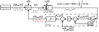
Charge-pump phase-locked loop (CP-PLL) is a modification of phase-locked loops with phase-frequency detector and square waveform signals. CP-PLL allows for a quick lock of the phase of the incoming signal, achieving low steady state phase error.
This page is based on this Wikipedia article Text is available under the CC BY-SA 4.0 license; additional terms may apply. Images, videos and audio are available under their respective licenses.