A discrete element method (DEM), also called a distinct element method, is any of a family of numerical methods for computing the motion and effect of a large number of small particles. Though DEM is very closely related to molecular dynamics, the method is generally distinguished by its inclusion of rotational degrees-of-freedom as well as stateful contact, particle deformation and often complicated geometries. With advances in computing power and numerical algorithms for nearest neighbor sorting, it has become possible to numerically simulate millions of particles on a single processor. Today DEM is becoming widely accepted as an effective method of addressing engineering problems in granular and discontinuous materials, especially in granular flows, powder mechanics, ice and rock mechanics. DEM has been extended into the Extended Discrete Element Method taking heat transfer, chemical reaction and coupling to CFD and FEM into account.

Computational fluid dynamics (CFD) is a branch of fluid mechanics that uses numerical analysis and data structures to analyze and solve problems that involve fluid flows. Computers are used to perform the calculations required to simulate the free-stream flow of the fluid, and the interaction of the fluid with surfaces defined by boundary conditions. With high-speed supercomputers, better solutions can be achieved, and are often required to solve the largest and most complex problems. Ongoing research yields software that improves the accuracy and speed of complex simulation scenarios such as transonic or turbulent flows. Initial validation of such software is typically performed using experimental apparatus such as wind tunnels. In addition, previously performed analytical or empirical analysis of a particular problem can be used for comparison. A final validation is often performed using full-scale testing, such as flight tests.

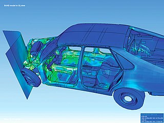
Computer-aided engineering (CAE) is the general usage of technology to aid in tasks related to engineering analysis. Any use of technology to solve or assist engineering issues falls under this umbrella.
Design for Six Sigma (DFSS) is a collection of best-practices for the development of new products and processes. It is sometimes deployed as an engineering design process or business process management method. DFSS originated at General Electric to build on the success they had with traditional Six Sigma; but instead of process improvement, DFSS was made to target new product development. It is used in many industries, like finance, marketing, basic engineering, process industries, waste management, and electronics. It is based on the use of statistical tools like linear regression and enables empirical research similar to that performed in other fields, such as social science. While the tools and order used in Six Sigma require a process to be in place and functioning, DFSS has the objective of determining the needs of customers and the business, and driving those needs into the product solution so created. It is used for product or process design in contrast with process improvement. Measurement is the most important part of most Six Sigma or DFSS tools, but whereas in Six Sigma measurements are made from an existing process, DFSS focuses on gaining a deep insight into customer needs and using these to inform every design decision and trade-off.
Bernard Roy Frieden is an American mathematical physicist.

A foundry is a factory that produces metal castings. Metals are cast into shapes by melting them into a liquid, pouring the metal into a mold, and removing the mold material after the metal has solidified as it cools. The most common metals processed are aluminum and cast iron. However, other metals, such as bronze, brass, steel, magnesium, and zinc, are also used to produce castings in foundries. In this process, parts of desired shapes and sizes can be formed.
Integrated Computational Materials Engineering (ICME) is an approach to design products, the materials that comprise them, and their associated materials processing methods by linking materials models at multiple length scales. Key words are "Integrated", involving integrating models at multiple length scales, and "Engineering", signifying industrial utility. The focus is on the materials, i.e. understanding how processes produce material structures, how those structures give rise to material properties, and how to select materials for a given application. The key links are process-structures-properties-performance. The National Academies report describes the need for using multiscale materials modeling to capture the process-structures-properties-performance of a material.

Directional solidification(DS) and progressive solidification are types of solidification within castings. Directional solidification is solidification that occurs from farthest end of the casting and works its way towards the sprue. Progressive solidification, also known as parallel solidification, is solidification that starts at the walls of the casting and progresses perpendicularly from that surface.
In software development, effort estimation is the process of predicting the most realistic amount of effort required to develop or maintain software based on incomplete, uncertain and noisy input. Effort estimates may be used as input to project plans, iteration plans, budgets, investment analyses, pricing processes and bidding rounds.
Finite element method (FEM) is a popular method for numerically solving differential equations arising in engineering and mathematical modeling. Typical problem areas of interest include the traditional fields of structural analysis, heat transfer, fluid flow, mass transport, and electromagnetic potential. Computers are usually used to perform the calculations required. With high-speed supercomputers, better solutions can be achieved and are often required to solve the largest and most complex problems.
RF microwave CAE CAD is computer-aided design (CAD) using computer technology to aid in the design, modeling, and simulation of an RF or microwave product. It is a visual and symbol-based method of communication whose conventions are particular to RF/microwave engineering.
modeFRONTIER is a software solution for simulation process automation and design exploration developed by ESTECO, an Italian engineering software house. modeFRONTIER leverages advanced optimization algorithms and methodologies and enables engineers to find optimal solutions for complex engineering problems. Its workflow-based environment and multi-objective optimization algorithms are used for streamlining the engineering design process and obtaining improved results.

Casting is a manufacturing process in which a liquid material is usually poured into a mold, which contains a hollow cavity of the desired shape, and then allowed to solidify. The solidified part is also known as a casting, which is ejected or broken out of the mold to complete the process. Casting materials are usually metals or various time setting materials that cure after mixing two or more components together; examples are epoxy, concrete, plaster and clay. Casting is most often used for making complex shapes that would be otherwise difficult or uneconomical to make by other methods. Heavy equipment like machine tool beds, ships' propellers, etc. can be cast easily in the required size, rather than fabricating by joining several small pieces. Casting is a 7,000-year-old process. The oldest surviving casting is a copper frog from 3200 BC.
Wei ShyyJP is an aerospace engineer who served as the 4th president of the Hong Kong University of Science and Technology (HKUST) from September 2018 to October 2022. He is currently a professor emeritus of mechanical and aerospace engineering at HKUST.

Generative design is an iterative design process that uses software to generate outputs that fulfill a set of constraints iteratively adjusted by a designer. Whether a human, test program, or artificial intelligence, the designer algorithmically or manually refines the feasible region of the program's inputs and outputs with each iteration to fulfill evolving design requirements. By employing computing power to evaluate more design permutations than a human alone is capable of, the process is capable of producing an optimal design that mimics nature's evolutionary approach to design through genetic variation and selection. The output can be images, sounds, architectural models, animation, and much more. It is, therefore, a fast method of exploring design possibilities that is used in various design fields such as art, architecture, communication design, and product design.
Simcenter Amesim is a commercial simulation software for the modeling and analysis of multi-domain systems. It is part of systems engineering domain and falls into the mechatronic engineering field.
Predictive engineering analytics (PEA) is a development approach for the manufacturing industry that helps with the design of complex products. It concerns the introduction of new software tools, the integration between those, and a refinement of simulation and testing processes to improve collaboration between analysis teams that handle different applications. This is combined with intelligent reporting and data analytics. The objective is to let simulation drive the design, to predict product behavior rather than to react on issues which may arise, and to install a process that lets design continue after product delivery.
Optimization Systems Associates (OSA) was founded by John Bandler in 1983. OSA produced the first commercial implementation of space mapping optimization to enhance the speed and accuracy of engineering design. OSA’s primary thrust was in computer-aided design (CAD) and simulation and optimization of radio-frequency and microwave circuits and systems. Its products included developments of Bandler's space mapping concept and methodology, which facilitates effective modeling and design optimization of computationally intensive engineering systems.
Titanium foams exhibit high specific strength, high energy absorption, excellent corrosion resistance and biocompatibility. These materials are ideally suited for applications within the aerospace industry. An inherent resistance to corrosion allows the foam to be a desirable candidate for various filtering applications. Further, titanium's physiological inertness makes its porous form a promising candidate for biomedical implantation devices. The largest advantage in fabricating titanium foams is that the mechanical and functional properties can be adjusted through manufacturing manipulations that vary porosity and cell morphology. The high appeal of titanium foams is directly correlated to a multi-industry demand for advancement in this technology.
Probabilistic numerics is an active field of study at the intersection of applied mathematics, statistics, and machine learning centering on the concept of uncertainty in computation. In probabilistic numerics, tasks in numerical analysis such as finding numerical solutions for integration, linear algebra, optimization and simulation and differential equations are seen as problems of statistical, probabilistic, or Bayesian inference.


