
A composite or composite material is a material which is produced from two or more constituent materials. These constituent materials have notably dissimilar chemical or physical properties and are merged to create a material with properties unlike the individual elements. Within the finished structure, the individual elements remain separate and distinct, distinguishing composites from mixtures and solid solutions. Composite materials with more than one distinct layer are called composite laminates.

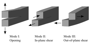
Fracture is the appearance of a crack or complete separation of an object or material into two or more pieces under the action of stress. The fracture of a solid usually occurs due to the development of certain displacement discontinuity surfaces within the solid. If a displacement develops perpendicular to the surface, it is called a normal tensile crack or simply a crack; if a displacement develops tangentially, it is called a shear crack, slip band, or dislocation.
Fracture mechanics is the field of mechanics concerned with the study of the propagation of cracks in materials. It uses methods of analytical solid mechanics to calculate the driving force on a crack and those of experimental solid mechanics to characterize the material's resistance to fracture.
Mohr–Coulomb theory is a mathematical model describing the response of brittle materials such as concrete, or rubble piles, to shear stress as well as normal stress. Most of the classical engineering materials follow this rule in at least a portion of their shear failure envelope. Generally the theory applies to materials for which the compressive strength far exceeds the tensile strength.

In applied mechanics, bending characterizes the behavior of a slender structural element subjected to an external load applied perpendicularly to a longitudinal axis of the element.

The three-point bending flexural test provides values for the modulus of elasticity in bending , flexural stress , flexural strain and the flexural stress–strain response of the material. This test is performed on a universal testing machine with a three-point or four-point bend fixture. The main advantage of a three-point flexural test is the ease of the specimen preparation and testing. However, this method has also some disadvantages: the results of the testing method are sensitive to specimen and loading geometry and strain rate.
The J-integral represents a way to calculate the strain energy release rate, or work (energy) per unit fracture surface area, in a material. The theoretical concept of J-integral was developed in 1967 by G. P. Cherepanov and independently in 1968 by James R. Rice, who showed that an energetic contour path integral was independent of the path around a crack.
A yield surface is a five-dimensional surface in the six-dimensional space of stresses. The yield surface is usually convex and the state of stress of inside the yield surface is elastic. When the stress state lies on the surface the material is said to have reached its yield point and the material is said to have become plastic. Further deformation of the material causes the stress state to remain on the yield surface, even though the shape and size of the surface may change as the plastic deformation evolves. This is because stress states that lie outside the yield surface are non-permissible in rate-independent plasticity, though not in some models of viscoplasticity.
Methods have been devised to modify the yield strength, ductility, and toughness of both crystalline and amorphous materials. These strengthening mechanisms give engineers the ability to tailor the mechanical properties of materials to suit a variety of different applications. For example, the favorable properties of steel result from interstitial incorporation of carbon into the iron lattice. Brass, a binary alloy of copper and zinc, has superior mechanical properties compared to its constituent metals due to solution strengthening. Work hardening has also been used for centuries by blacksmiths to introduce dislocations into materials, increasing their yield strengths.
The Hill yield criterion developed by Rodney Hill, is one of several yield criteria for describing anisotropic plastic deformations. The earliest version was a straightforward extension of the von Mises yield criterion and had a quadratic form. This model was later generalized by allowing for an exponent m. Variations of these criteria are in wide use for metals, polymers, and certain composites.

Viscoplasticity is a theory in continuum mechanics that describes the rate-dependent inelastic behavior of solids. Rate-dependence in this context means that the deformation of the material depends on the rate at which loads are applied. The inelastic behavior that is the subject of viscoplasticity is plastic deformation which means that the material undergoes unrecoverable deformations when a load level is reached. Rate-dependent plasticity is important for transient plasticity calculations. The main difference between rate-independent plastic and viscoplastic material models is that the latter exhibit not only permanent deformations after the application of loads but continue to undergo a creep flow as a function of time under the influence of the applied load.

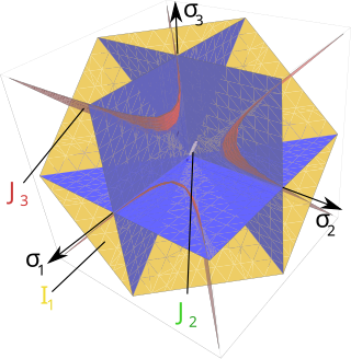
The Drucker–Prager yield criterion is a pressure-dependent model for determining whether a material has failed or undergone plastic yielding. The criterion was introduced to deal with the plastic deformation of soils. It and its many variants have been applied to rock, concrete, polymers, foams, and other pressure-dependent materials.

The Bresler–Pister yield criterion is a function that was originally devised to predict the strength of concrete under multiaxial stress states. This yield criterion is an extension of the Drucker–Prager yield criterion and can be expressed on terms of the stress invariants as
Material failure theory is an interdisciplinary field of materials science and solid mechanics which attempts to predict the conditions under which solid materials fail under the action of external loads. The failure of a material is usually classified into brittle failure (fracture) or ductile failure (yield). Depending on the conditions most materials can fail in a brittle or ductile manner or both. However, for most practical situations, a material may be classified as either brittle or ductile.
The Tsai–Wu failure criterion is a phenomenological material failure theory which is widely used for anisotropic composite materials which have different strengths in tension and compression. The Tsai-Wu criterion predicts failure when the failure index in a laminate reaches 1. This failure criterion is a specialization of the general quadratic failure criterion proposed by Gol'denblat and Kopnov and can be expressed in the form
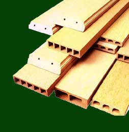
A fiber-reinforced composite (FRC) is a composite building material that consists of three components:
- the fibers as the discontinuous or dispersed phase,
- the matrix as the continuous phase, and
- the fine interphase region, also known as the interface.

Sandwich theory describes the behaviour of a beam, plate, or shell which consists of three layers—two facesheets and one core. The most commonly used sandwich theory is linear and is an extension of first-order beam theory. The linear sandwich theory is of importance for the design and analysis of sandwich panels, which are of use in building construction, vehicle construction, airplane construction and refrigeration engineering.
The Christensen failure criterion is a material failure theory for isotropic materials that attempts to span the range from ductile to brittle materials. It has a two-property form calibrated by the uniaxial tensile and compressive strengths T and C .
In materials science, toughening refers to the process of making a material more resistant to the propagation of cracks. When a crack propagates, the associated irreversible work in different materials classes is different. Thus, the most effective toughening mechanisms differ among different materials classes. The crack tip plasticity is important in toughening of metals and long-chain polymers. Ceramics have limited crack tip plasticity and primarily rely on different toughening mechanisms.
The Tsai–Hill failure criterion is one of the phenomenological material failure theories, which is widely used for anisotropic composite materials which have different strengths in tension and compression. The Tsai-Hill criterion predicts failure when the failure index in a laminate reaches 1.


