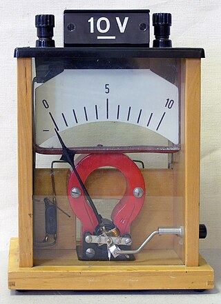
A voltmeter is an instrument used for measuring electric potential difference between two points in an electric circuit. It is connected in parallel. It usually has a high resistance so that it takes negligible current from the circuit.
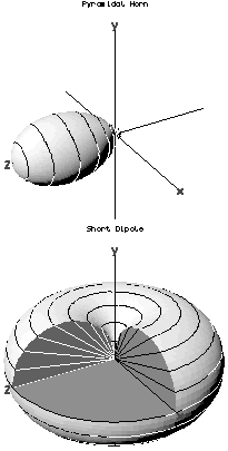
In the field of antenna design the term radiation pattern refers to the directional (angular) dependence of the strength of the radio waves from the antenna or other source.

In radio engineering and telecommunications, standing wave ratio (SWR) is a measure of impedance matching of loads to the characteristic impedance of a transmission line or waveguide. Impedance mismatches result in standing waves along the transmission line, and SWR is defined as the ratio of the partial standing wave's amplitude at an antinode (maximum) to the amplitude at a node (minimum) along the line.

A time-domain reflectometer (TDR) is an electronic instrument used to determine the characteristics of electrical lines by observing reflected pulses.

A waveguide is a structure that guides waves, such as sound, light, radio waves or other electromagnetic waves, with minimal loss of energy by restricting the transmission of energy to one direction. Without the physical constraint of a waveguide, wave intensities decrease according to the inverse square law as they expand into three-dimensional space.
In telecommunications, signal reflection occurs when a signal is transmitted along a transmission medium, such as a copper cable or an optical fiber. Some of the signal power may be reflected back to its origin rather than being carried all the way along the cable to the far end. This happens because imperfections in the cable cause impedance mismatches and non-linear changes in the cable characteristics. These abrupt changes in characteristics cause some of the transmitted signal to be reflected. In radio frequency (RF) practice this is often measured in a dimensionless ratio known as voltage standing wave ratio (VSWR) with a VSWR bridge. The ratio of energy bounced back depends on the impedance mismatch. Mathematically, it is defined using the reflection coefficient.

A microphone, colloquially called mic or mike, is a transducer that converts sound into an electrical signal. Microphones are used in many applications such as telephones, hearing aids, public address systems for concert halls and public events, motion picture production, live and recorded audio engineering, sound recording, two-way radios, megaphones, and radio and television broadcasting. They are also used in computers for recording voice, speech recognition, VoIP, and for other purposes such as ultrasonic sensors or knock sensors.

In radio engineering, an antenna or aerial is the interface between radio waves propagating through space and electric currents moving in metal conductors, used with a transmitter or receiver. In transmission, a radio transmitter supplies an electric current to the antenna's terminals, and the antenna radiates the energy from the current as electromagnetic waves. In reception, an antenna intercepts some of the power of a radio wave in order to produce an electric current at its terminals, that is applied to a receiver to be amplified. Antennas are essential components of all radio equipment.
This is an index of articles relating to electronics and electricity or natural electricity and things that run on electricity and things that use or conduct electricity.
In electrical engineering, partial discharge (PD) is a localized dielectric breakdown (DB) of a small portion of a solid or fluid electrical insulation (EI) system under high voltage (HV) stress. While a corona discharge (CD) is usually revealed by a relatively steady glow or brush discharge (BD) in air, partial discharges within solid insulation system are not visible.

The input impedance of an electrical network is the measure of the opposition to current (impedance), both static (resistance) and dynamic (reactance), into a load network that is external to the electrical source network. The input admittance is a measure of the load network's propensity to draw current. The source network is the portion of the network that transmits power, and the load network is the portion of the network that consumes power.
Scattering parameters or S-parameters describe the electrical behavior of linear electrical networks when undergoing various steady state stimuli by electrical signals.

The standing wave ratio meter, SWR meter, ISWR meter, or VSWR meter measures the standing wave ratio (SWR) in a transmission line. The meter indirectly measures the degree of mismatch between a transmission line and its load. Electronics technicians use it to adjust radio transmitters and their antennas and feedlines to be impedance matched so they work together properly, and evaluate the effectiveness of other impedance matching efforts.

In electronics, a Lecher line or Lecher wires is a pair of parallel wires or rods that were used to measure the wavelength of radio waves, mainly at VHF, UHF and microwave frequencies. They form a short length of balanced transmission line. When attached to a source of radio-frequency power such as a radio transmitter, the radio waves form standing waves along their length. By sliding a conductive bar that bridges the two wires along their length, the length of the waves can be physically measured. Austrian physicist Ernst Lecher, improving on techniques used by Oliver Lodge and Heinrich Hertz, developed this method of measuring wavelength around 1888. Lecher lines were used as frequency measuring devices until frequency counters became available after World War 2. They were also used as components, often called "resonant stubs", in VHF, UHF and microwave radio equipment such as transmitters, radar sets, and television sets, serving as tank circuits, filters, and impedance-matching devices. They are used at frequencies between HF/VHF, where lumped components are used, and UHF/SHF, where resonant cavities are more practical.
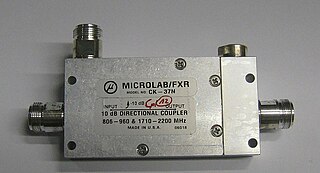
Power dividers and directional couplers are passive devices used mostly in the field of radio technology. They couple a defined amount of the electromagnetic power in a transmission line to a port enabling the signal to be used in another circuit. An essential feature of directional couplers is that they only couple power flowing in one direction. Power entering the output port is coupled to the isolated port but not to the coupled port. A directional coupler designed to split power equally between two ports is called a hybrid coupler.

A variety of types of electrical transformer are made for different purposes. Despite their design differences, the various types employ the same basic principle as discovered in 1831 by Michael Faraday, and share several key functional parts.
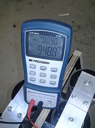
An LCR meter is a type of electronic test equipment used to measure the inductance (L), capacitance (C), and resistance (R) of an electronic component. In the simpler versions of this instrument the impedance was measured internally and converted for display to the corresponding capacitance or inductance value. Readings should be reasonably accurate if the capacitor or inductor device under test does not have a significant resistive component of impedance. More advanced designs measure true inductance or capacitance, as well as the equivalent series resistance of capacitors and the Q factor of inductive components.
A signal travelling along an electrical transmission line will be partly, or wholly, reflected back in the opposite direction when the travelling signal encounters a discontinuity in the characteristic impedance of the line, or if the far end of the line is not terminated in its characteristic impedance. This can happen, for instance, if two lengths of dissimilar transmission lines are joined.

A measuring instrument is a device to measure a physical quantity. In the physical sciences, quality assurance, and engineering, measurement is the activity of obtaining and comparing physical quantities of real-world objects and events. Established standard objects and events are used as units, and the process of measurement gives a number relating the item under study and the referenced unit of measurement. Measuring instruments, and formal test methods which define the instrument's use, are the means by which these relations of numbers are obtained. All measuring instruments are subject to varying degrees of instrument error and measurement uncertainty. These instruments may range from simple objects such as rulers and stopwatches to electron microscopes and particle accelerators. Virtual instrumentation is widely used in the development of modern measuring instruments.

Slotted lines are used for microwave measurements and consist of a movable probe inserted into a slot in a transmission line. They are used in conjunction with a microwave power source and usually, in keeping with their low-cost application, a low cost Schottky diode detector and VSWR meter rather than an expensive microwave power meter.


