Slotted line

Last updated

Figure 1. Waveguide slotted line Waveguide slotted line.jpg
Figure 1. Waveguide slotted line

Slotted lines are used for microwave measurements and consist of a movable probe inserted into a slot in a transmission line. They are used in conjunction with a microwave power source and usually, in keeping with their low-cost application, a low cost Schottky diode detector and VSWR meter rather than an expensive microwave power meter.

Contents

Slotted lines can measure standing waves, wavelength, and, with some calculation or plotting on Smith charts, a number of other parameters including reflection coefficient and electrical impedance. A precision variable attenuator is often incorporated in the test setup to improve accuracy. This is used to make level measurements, while the detector and VSWR meter are retained only to mark a reference point for the attenuator to be set to, thus eliminating entirely the detector and meter measurement errors. The parameter most commonly measured by a slotted line is SWR. This serves as a measure of the accuracy of the impedance match to the item under test. This is especially important for transmitting antennas and their feed lines; high standing wave ratio on a radio or TV antenna can distort the signal, increase transmission line loss and potentially damage components in the transmission path, possibly even the transmitter.

Slotted lines are no longer widely used, but can still be found in budget applications. Their main drawback is that they are labour-intensive to use and require calculation, tables, or plotting to make use of the results. They need to be made with mechanical precision and the probe and its detector need to be adjusted with care, but they can give very accurate results.

Description

The slotted line is one of the basic instruments used in radio frequency test and measurement at microwave frequencies. It consists of a precision transmission line, usually co-axial but waveguide implementations are also used, with a movable insulated probe inserted into a longitudinal slot cut into the line. In a co-axial slotted line, the slot is cut into the outer conductor of the line. The probe is inserted past the outer conductor, but not so far that it touches the inner conductor. In a rectangular waveguide, the slot is usually cut along the centre of the broad wall of the waveguide. Circular waveguide slotted lines are also possible. [1]

Slotted lines are relatively cheap [note 1] and can perform many of the measurements done by more expensive equipment such as network analysers. However, slotted line measurement techniques are more labour-intensive and often do not directly output the desired parameter; some calculation or plotting is frequently required. In particular, they can only carry out a measurement at one spot frequency at a time so producing a plot of a parameter versus frequency is very time consuming. This is to be compared to modern instruments like network and spectrum analysers which are intrinsically frequency swept and produce a plot instantly. Slotted lines have now largely been superseded, but are still found where capital costs are an issue. Their remaining uses are mostly in the millimetre band, where modern test apparatus is either prohibitively expensive or not available at all, and with academic laboratories and hobbyists. They are also useful as a teaching aid as the user is more directly exposed to basic line phenomena than with more sophisticated instruments. [2]

Operation

The slotted line works by sampling the electric field inside the transmission line with the probe. For accuracy, it is important that the probe disturbs the field as little as possible. For this reason the probe diameter and slot width are kept small (usually around 1 mm) and the probe is inserted in no further than necessary. It is also necessary in waveguide slotted lines to place the slot at a position where the current in the waveguide walls is parallel to the slot. The current will then not be disturbed by the presence of the slot as long as it is not too wide. For the dominant mode this is on the centre-line of the broad face of the waveguide, but for some other modes it may need to be off-centre. This is not an issue for the co-axial line because this operates in the TEM (transverse electromagnetic) mode and hence the current is everywhere parallel to the slot. The slot may be tapered at its ends to avoid discontinuities causing reflections. [3]

The disturbance to the field inside the line caused by the insertion of the probe is minimised as far as possible. There are two parts to this disturbance. The first part is due to the power the probe has extracted from the line and manifests as a lumped equivalent circuit of a resistor. This is minimised by limiting the distance the probe is inserted into the line so that only enough power is extracted for the detector to operate effectively. The second part of the disturbance is due to energy stored in the field around the probe and manifests as a lumped equivalent of a capacitor. This capacitance can be cancelled out with an inductance of equal and opposite impedance. Lumped inductors are not practical at microwave frequencies; instead, an adjustable stub with an inductive equivalent circuit is used to "tune out" the probe capacitance. The result is an equivalent circuit of a high impedance in shunt across the line which has little effect on the transmitted power in the line. The probe is more sensitive as a result of this tuning and the distance it is inserted can be further limited as a result. [4]

Test setup

Figure 2. A test setup using a waveguide slotted line Annotated slotted line test station.png
Figure 2. A test setup using a waveguide slotted line
Figure 3. Co-axial slotted line Slotted line.png
Figure 3. Co-axial slotted line

A typical test setup with a waveguide slotted line is shown in figure 2. Referring to this figure, power from a test equipment source (not shown) enters the apparatus through the co-axial cable on the left and is converted to waveguide format by means of a launcher (1). This is followed by a section of waveguide (2) providing a transition to a smaller size of guide. An important component in the setup is the isolator (3) which prevents power being reflected back into the source. Depending on the test conditions, such reflections can be large and a high-power source may be damaged by the returning wave. The power entering the slotted line is controlled by a rotary variable attenuator (4). This is followed by the slotted line itself (5) above which is the probe mounted on a movable carriage. The carriage also carries the probe adjustments: (6) is the probe depth adjustment, (7) is a length of co-axial section with tuning adjustments, and (8) is a detector, which uses either a point contact crystal rectifier or a Schottky barrier diode. [5] The right-hand end of the slotted line is terminated in a matched load (9) which absorbs all the power exiting the end of the waveguide. The load can be replaced by the component or system that it is desired to test. It can also be replaced with a reference short-circuit (10) which is used to calibrate the slotted line. The carriage can be moved along the slotted line by means of a rotary knob (11) which simultaneously moves a vernier gauge (12) for accurate measurement of the probes position along the line. [6]

The probe is connected to a detector and a display meter (not shown in figure 2). These can be, respectively, a thermistor and power meter, or an envelope detector and VSWR meter. The detector can be a crystal detector or a Schottky barrier diode. The detector is mounted on the probe assembly, usually a distance λ/4 [note 2] from the probe tip as shown in figure 3. This is because the detector looks almost like a short circuit to the transmission line, and this distance will convert it to an open circuit through the quarter-wave impedance transformer effect. Thus, the detector has minimal effect on loading the line. The probe tuning stub can be seen on figure 3 branching from the line linking the probe to the detector. Figure 2 has a slightly different arrangement; the main probe into the waveguide leads to a vertical co-axial tuning and adjustment section but the detector is on a horizontal side-section with a secondary probe into the upright co-axial section. [7]

Measurements

Measurements of microwave power can be made directly, usually with a thermistor based detector and meter. However, these instruments are expensive and a common meter used in measurements with a slotted line is instead a cheaper low-frequency VSWR meter. The microwave power source is amplitude modulated with, typically, a 1 kHz signal which is recovered by the envelope detector in the probe and sent to the VSWR meter. This scheme is preferred to simply detecting the unmodulated carrier directly, which would result in a DC output, because a stable, narrowband, tuned amplifier can be used to amplify the 1 kHz signal. A large amplification is required in the VSWR meter because the limit of the square law range [note 3] of the detector diode is no more than 10 μW. [8]

Maxima and minima

Figure 4. Standing wave patterns on a line for various reflection coefficients showing maxima and minima Standing Wave Ratio.svg
Figure 4. Standing wave patterns on a line for various reflection coefficients showing maxima and minima

When the slotted line is terminated with a precision matching load there is no variation in the detected power along the line, other than a very small decrease due to losses in the line. However, when this is replaced by a device under test (DUT) which is not perfectly matched to the line there will be a reflection back towards the source. This causes a standing wave to be set up on the line with periodic maxima and minima (collectively, extrema) due to alternating constructive and destructive interference. These extrema are found by moving the probe back and forth along the line and the level at that point can then be measured on the meter. [9]

The extrema are not of any great interest in themselves, but are used in the calculation of several more useful parameters. Some of these parameters require the measurement of the exact position of the extremum. Either maxima or minima can equally be used, from a mathematical point of view, but minima are preferred because they are always much sharper than maxima, especially for large reflections, as shown in figure 4. Additionally, the probe causes less disturbance to the field near a minimum than it does near a maximum. [10]

Wavelength

Wavelength is determined by measuring the distance between two adjacent minima. This distance will be λ/2. There is no need for a DUT, better results are obtained with the reference short in position. [11]

Standing wave ratio

Standing wave ratio (SWR or VSWR) is a basic parameter and the one most commonly measured on a slotted line. This quantity is of particular importance for transmitter antennae. A high SWR indicates a poor match between the feed line and the antenna, which increases wasted power, can cause damage to components in the transmission path, possibly including the transmitter, and cause distortion to TV, FM stereo and digital signals. With the input power set so that the maxima are at 0 dBm, a measurement of a minimum in decibels will directly give SWR (after discarding the minus sign). [12]

Reflection coefficient

The reflection coefficient, ρ, is the ratio of the reflected wave to the incident wave. In general it is a complex number. The magnitude of the reflection coefficient can be calculated from the VSWR measurement by,

where VSWR is the standing wave ratio expressed as a voltage ratio (not in decibels). However, to completely characterise the reflection coefficient, the phase of ρ must also be found. This is done on a slotted line by measuring the distance of the first minimum from the DUT. Moving the probe right up to the DUT is not practicable so a different approach is usually adopted. The position of the first minimum when the reference short is in place is noted. The distance back along the line from this reference point to the next minimum when the DUT is in place will be the same as the distance from the DUT to the first minimum. This is so because the reference short guarantees a minimum at the DUT position. [13]

The phase part of ρ is given by,

where λ is the wavelength and x is the distance to the first minimum as described earlier. The magnitude and phase representation of ρ can, if required, be expressed as real and imaginary parts instead by the usual manipulation of complex numbers. [14]

Impedance

The impedance, Z, of the DUT can be calculated from the reflection coefficient by,

where Z0 is the characteristic impedance of the line. An alternative method is to plot the VSWR and distance to the node (in wavelengths) on a Smith chart. These quantities are directly measured by the slotted line. From this plot the DUT impedance (normalised to Z0) can be read directly off the Smith chart. [15]

Accuracy considerations

Good slotted lines are precision made instruments. They need to be because mechanical defects can affect accuracy. Some of the mechanical issues that are relevant to this include backlash of the vernier, concentricity of the inner and outer conductor, circularity of the outer conductor, centrality and straightness of the inner conductor, variations in cross-section, and the ability of the carriage to maintain a constant probe depth. Issues with probe tuning and disturbances to the field have already been discussed, but the insulated spacers holding the centre conductor in place can also disturb the field. Consequently, these are made as discrete as is compatible with mechanical strength. However, the greatest source of inaccuracy is usually not the slotted line itself, but the characteristics of the detector diode. [16]

The detected voltage signal output of the Schottky barrier diodes typically used in microwave detectors have a square law relationship to the power being measured and meters are calibrated accordingly. However, as the power increases, the diode deviates significantly from a square law and remains accurate up to an output voltage of only around 5-10 mV. This can be improved a little by adding a load resistor to the detector output, but this also has the undesirable effect of decreasing sensitivity. Another technique is to reduce the range of power being measured (so that it is brought within the square law range of the detector) by measuring at a point other than a maximum. The maximum is then calculated from the known mathematical shape of the standing wave pattern. This has the objection that it adds significantly to the labour required to make the measurements, as does the technique of precisely calibrating the detector and adjusting the readings on the meter according to a calibration chart. [17]

It is possible to completely eliminate errors in the detector and meter if a precision variable attenuator is used in the test setup. In this technique a minimum is first found and the attenuator adjusted so that the meter is indicating precisely some convenient mark. A maximum is then found and the attenuation increased until the meter is indicating the same mark. The amount the attenuation had to be increased is the VSWR of the standing wave. Accuracy here depends on the accuracy of the attenuator and not at all on the detector. [18]

Notes

  1. Thomas H. Lee even describes a microstrip slotted line for use up to 5 GHz that he claims can be made for less than $10. He calls this a "40 dB cost reduction" over the price of a network analyser. That is, its cost is 10,000 times less than an analyser costing $100,000 (Lee, pages xv, 268-271).
  2. λ, the customary symbol for wavelength. It is usually most convenient to give distances on transmission lines in terms of wavelengths of the transmitted wave, or sometimes, when the distance involved is small or not an exact multiple of a quarter wavelength, in radians where θ=2πλ radians.
  3. square law, of a detector diode, the range over which the demodulated output voltage is proportional to the square of the carrier voltage on the line.

Related Research Articles

<span class="mw-page-title-main">Microwave</span> Electromagnetic radiation with wavelengths from 1 m to 1 mm

Microwave is a form of electromagnetic radiation with wavelengths ranging from about one meter to one millimeter corresponding to frequencies between 300 MHz and 300 GHz respectively. Different sources define different frequency ranges as microwaves; the above broad definition includes both UHF and EHF bands. A more common definition in radio-frequency engineering is the range between 1 and 100 GHz. In all cases, microwaves include the entire SHF band at minimum. Frequencies in the microwave range are often referred to by their IEEE radar band designations: S, C, X, Ku, K, or Ka band, or by similar NATO or EU designations.

The propagation constant of a sinusoidal electromagnetic wave is a measure of the change undergone by the amplitude and phase of the wave as it propagates in a given direction. The quantity being measured can be the voltage, the current in a circuit, or a field vector such as electric field strength or flux density. The propagation constant itself measures the change per unit length, but it is otherwise dimensionless. In the context of two-port networks and their cascades, propagation constant measures the change undergone by the source quantity as it propagates from one port to the next.

In radio engineering and telecommunications, standing wave ratio (SWR) is a measure of impedance matching of loads to the characteristic impedance of a transmission line or waveguide. Impedance mismatches result in standing waves along the transmission line, and SWR is defined as the ratio of the partial standing wave's amplitude at an antinode (maximum) to the amplitude at a node (minimum) along the line.

<span class="mw-page-title-main">Waveguide</span> Structure that guides waves efficiently

A waveguide is a structure that guides waves, such as electromagnetic waves or sound, with minimal loss of energy by restricting the transmission of energy to one direction. Without the physical constraint of a waveguide, wave intensities decrease according to the inverse square law as they expand into three-dimensional space.

This is an index of articles relating to electronics and electricity or natural electricity and things that run on electricity and things that use or conduct electricity.

Super high frequency (SHF) is the ITU designation for radio frequencies (RF) in the range between 3 and 30 gigahertz (GHz). This band of frequencies is also known as the centimetre band or centimetre wave as the wavelengths range from one to ten centimetres. These frequencies fall within the microwave band, so radio waves with these frequencies are called microwaves. The small wavelength of microwaves allows them to be directed in narrow beams by aperture antennas such as parabolic dishes and horn antennas, so they are used for point-to-point communication and data links and for radar. This frequency range is used for most radar transmitters, wireless LANs, satellite communication, microwave radio relay links, satellite phones, and numerous short range terrestrial data links. They are also used for heating in industrial microwave heating, medical diathermy, microwave hyperthermy to treat cancer, and to cook food in microwave ovens.

<span class="mw-page-title-main">Horn antenna</span> Funnel-shaped waveguide radio device

A horn antenna or microwave horn is an antenna that consists of a flaring metal waveguide shaped like a horn to direct radio waves in a beam. Horns are widely used as antennas at UHF and microwave frequencies, above 300 MHz. They are used as feed antennas for larger antenna structures such as parabolic antennas, as standard calibration antennas to measure the gain of other antennas, and as directive antennas for such devices as radar guns, automatic door openers, and microwave radiometers. Their advantages are moderate directivity, broad bandwidth, low losses, and simple construction and adjustment.

<span class="mw-page-title-main">RF switch</span>

An RF switch or microwave switch is a device to route high frequency signals through transmission paths. RF and microwave switches are used extensively in microwave test systems for signal routing between instruments and devices under test (DUT). Incorporating a switch into a switch matrix system enables you to route signals from multiple instruments to single or multiple DUTs. This allows multiple tests to be performed with the same setup, eliminating the need for frequent connects and disconnects. The entire testing process can be automated, increasing the throughput in high-volume production environments.

<span class="mw-page-title-main">Network analyzer (electrical)</span>

A network analyzer is an instrument that measures the network parameters of electrical networks. Today, network analyzers commonly measure s–parameters because reflection and transmission of electrical networks are easy to measure at high frequencies, but there are other network parameter sets such as y-parameters, z-parameters, and h-parameters. Network analyzers are often used to characterize two-port networks such as amplifiers and filters, but they can be used on networks with an arbitrary number of ports.

<span class="mw-page-title-main">SWR meter</span> Measurement device for radio equipment

The standing wave ratio meter, SWR meter, ISWR meter, or VSWR meter measures the standing wave ratio (SWR) in a transmission line. The meter indirectly measures the degree of mismatch between a transmission line and its load. Electronics technicians use it to adjust radio transmitters and their antennas and feedlines to be impedance matched so they work together properly, and evaluate the effectiveness of other impedance matching efforts.

<span class="mw-page-title-main">Waveguide (radio frequency)</span> Hollow metal pipe used to carry radio waves

In radio-frequency engineering and communications engineering, waveguide is a hollow metal pipe used to carry radio waves. This type of waveguide is used as a transmission line mostly at microwave frequencies, for such purposes as connecting microwave transmitters and receivers to their antennas, in equipment such as microwave ovens, radar sets, satellite communications, and microwave radio links.

A radio transmitter or receiver is connected to an antenna which emits or receives the radio waves. The antenna feed system or antenna feed is the cable or conductor, and other associated equipment, which connects the transmitter or receiver with the antenna and makes the two devices compatible. In a radio transmitter, the transmitter generates an alternating current of radio frequency, and the feed system feeds the current to the antenna, which converts the power in the current to radio waves. In a radio receiver, the incoming radio waves excite tiny alternating currents in the antenna, and the feed system delivers this current to the receiver, which processes the signal.

<span class="mw-page-title-main">Test probe</span>

A test probe is a physical device used to connect electronic test equipment to a device under test (DUT). Test probes range from very simple, robust devices to complex probes that are sophisticated, expensive, and fragile. Specific types include test prods, oscilloscope probes and current probes. A test probe is often supplied as a test lead, which includes the probe, cable and terminating connector.

Load-pull is the colloquial term applied to the process of systematically varying the impedance presented to a device under test (DUT), most often a transistor, to assess its performance and the associated conditions to deliver that performance in a network. While load-pull itself implies impedance variation at the load port, impedance can also be varied at any of the ports of the DUT, most often at the source.

Mismatch loss in transmission line theory is the amount of power expressed in decibels that will not be available on the output due to impedance mismatches and signal reflections. A transmission line that is properly terminated, that is, terminated with the same impedance as that of the characteristic impedance of the transmission line, will have no reflections and therefore no mismatch loss. Mismatch loss represents the amount of power wasted in the system. It can also be thought of as the amount of power gained if the system was perfectly matched. Impedance matching is an important part of RF system design; however, in practice there will likely be some degree of mismatch loss. In real systems, relatively little loss is due to mismatch loss and is often on the order of 1dB.

<span class="mw-page-title-main">Reflections of signals on conducting lines</span> Electrical waves in return direction

A signal travelling along an electrical transmission line will be partly, or wholly, reflected back in the opposite direction when the travelling signal encounters a discontinuity in the characteristic impedance of the line, or if the far end of the line is not terminated in its characteristic impedance. This can happen, for instance, if two lengths of dissimilar transmission lines are joined.

<span class="mw-page-title-main">Waveguide filter</span> Electronic filter that is constructed with waveguide technology

A waveguide filter is an electronic filter constructed with waveguide technology. Waveguides are hollow metal conduits inside which an electromagnetic wave may be transmitted. Filters are devices used to allow signals at some frequencies to pass, while others are rejected. Filters are a basic component of electronic engineering designs and have numerous applications. These include selection of signals and limitation of noise. Waveguide filters are most useful in the microwave band of frequencies, where they are a convenient size and have low loss. Examples of microwave filter use are found in satellite communications, telephone networks, and television broadcasting.

<span class="mw-page-title-main">Waffle-iron filter</span> Type of waveguide filter

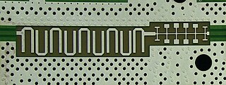
A waffle-iron filter is a type of waveguide filter used at microwave frequencies for signal filtering. It is a variation of the corrugated-waveguide filter but with longitudinal slots cut through the corrugations resulting in an internal structure that has the appearance of a waffle-iron.

<span class="mw-page-title-main">Planar transmission line</span> Transmission lines with flat ribbon-like conducting or dielectric lines

Planar transmission lines are transmission lines with conductors, or in some cases dielectric (insulating) strips, that are flat, ribbon-shaped lines. They are used to interconnect components on printed circuits and integrated circuits working at microwave frequencies because the planar type fits in well with the manufacturing methods for these components. Transmission lines are more than simply interconnections. With simple interconnections, the propagation of the electromagnetic wave along the wire is fast enough to be considered instantaneous, and the voltages at each end of the wire can be considered identical. If the wire is longer than a large fraction of a wavelength, these assumptions are no longer true and transmission line theory must be used instead. With transmission lines, the geometry of the line is precisely controlled so that its electrical behaviour is highly predictable. At lower frequencies, these considerations are only necessary for the cables connecting different pieces of equipment, but at microwave frequencies the distance at which transmission line theory becomes necessary is measured in millimetres. Hence, transmission lines are needed within circuits.

<span class="mw-page-title-main">Distributed-element circuit</span> Electrical circuits composed of lengths of transmission lines or other distributed components

Distributed-element circuits are electrical circuits composed of lengths of transmission lines or other distributed components. These circuits perform the same functions as conventional circuits composed of passive components, such as capacitors, inductors, and transformers. They are used mostly at microwave frequencies, where conventional components are difficult to implement.

References

  1. Multiple sources:
    • Gupta, page 113
    • Voltmer, pages 146–147
  2. Multiple sources:
    • Das & Das, page 496
    • Lee, pages 246, 251, 268
    • Voltmer, page 146
  3. Multiple sources:
    • Das & Das, pages 497–498
    • Gupta, page 113
  4. Voltmer, page 148
  5. H. C. Torrey, C. A. Whitmer, Crystal Rectifiers, New York: McGraw-Hill, 1948
  6. Das & Das, pages 496–498
  7. Das & Das, pages 496–497
  8. Multiple sources:
    • Das & Das, page 496
    • Voltmer, page 147
  9. Gupta, pages 113–114
  10. Voltmer, pages 147–148
  11. Multiple sources:
    • Das & Das, page 498
    • Voltmer, page 148
  12. Gupta, pages 112–113
  13. Multiple sources:
    • Gupta, pages 112–113
    • Lee, pages 248–249
  14. Multiple sources:
    • Connor, pages 29–32
    • Das & Das, page 498, 514-515
    • Lee, pages 248–249
  15. Multiple sources:
    • Connor, pages 34–38
    • Das & Das, pages 514–515
    • Gupta, page 112, 114
  16. Lee, pages 251–252
  17. Lee, pages 252–254
  18. Lee, page 253

Bibliography