
The Decca Navigator System was a hyperbolic radio navigation system that allowed ships and aircraft to determine their position by using radio signals from a dedicated system of static radio transmitters. The system used phase comparison between pairs of low frequency signals between 70 and 129 kHz, as opposed to pulse timing systems like Gee and LORAN. This made it much easier to design receivers using 1940s electronics, and operation was simplified by giving a direct readout of Decca coordinates without the complexity of a cathode-ray tube and highly skilled operator.

Radar is a system that uses radio waves to determine the distance (ranging), direction, and radial velocity of objects relative to the site. It is a radiodetermination method used to detect and track aircraft, ships, spacecraft, guided missiles, motor vehicles, map weather formations, and terrain.

A Doppler radar is a specialized radar that uses the Doppler effect to produce velocity data about objects at a distance. It does this by bouncing a microwave signal off a desired target and analyzing how the object's motion has altered the frequency of the returned signal. This variation gives direct and highly accurate measurements of the radial component of a target's velocity relative to the radar. The term applies to radar systems in many domains like aviation, police radar detectors, navigation, meteorology, etc.

MISTRAM was a high-resolution tracking system used by the United States Air Force to provide highly detailed trajectory analysis of rocket launches.

An emergency position-indicating radiobeacon (EPIRB) is a type of emergency locator beacon for commercial and recreational boats, a portable, battery-powered radio transmitter used in emergencies to locate boaters in distress and in need of immediate rescue. In the event of an emergency, such as a ship sinking or medical emergency onboard, the transmitter is activated and begins transmitting a continuous 406 MHz distress radio signal, which is used by search-and-rescue teams to quickly locate the emergency and render aid. The signal is detected by satellites operated by an international consortium of rescue services, COSPAS-SARSAT, which can detect emergency beacons anywhere on Earth transmitting on the distress frequency of 406 MHz. The satellites calculate the position or utilize the GPS coordinates of the beacon and quickly passes the information to the appropriate local first responder organization, which performs the search and rescue. As Search and Rescue approach the search areas, they use Direction Finding (DF) equipment to locate the beacon using the 121.5 MHz homing signal, or in newer EPIRBs, the AIS location signal. The basic purpose of this system is to help rescuers find survivors within the so-called "golden day" during which the majority of survivors can usually be saved. The feature distinguishing a modern EPIRB, often called GPIRB, from other types of emergency beacon is that it contains a GPS receiver and broadcasts its position, usually accurate within 100 m (330 ft), to facilitate location. Previous emergency beacons without a GPS can only be localized to within 2 km (1.2 mi) by the COSPAS satellites and relied heavily upon the 121.5 MHz homing signal to pin-point the beacons location as they arrived on scene.

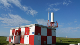
Very High Frequency Omnidirectional Range Station (VOR) is a type of short-range VHF radio navigation system for aircraft, enabling aircraft with a VOR receiver to determine the azimuth, referenced to magnetic north, between the aircraft to/from fixed VOR ground radio beacons. VOR and the first DME(1950) system to provide the slant range distance, were developed in the United States as part of a U.S. civil/military programm for Aeronautical Navigation Aids in 1945. Deployment of VOR and DME(1950) began in 1949 by the U.S. CAA. ICAO standardized VOR and DME(1950) in 1950 in ICAO Annex ed.1. Frequencies for the use of VOR are standardized in the very high frequency (VHF) band between 108.00 and 117.95 MHz Chapter 3, Table A. To improve azimuth accuracy of VOR even under difficult siting conditions, Doppler VOR (DVOR) was developed in the 1960s. VOR is according to ICAO rules a primary means navigation system for commercial and general aviation, (D)VOR are gradually decommissioned and replaced by DME-DME RNAV 7.2.3 and satellite based navigation systems such as GPS in the early 21st century. In 2000 there were about 3,000 VOR stations operating around the world, including 1,033 in the US, but by 2013 the number in the US had been reduced to 967. The United States is decommissioning approximately half of its VOR stations and other legacy navigation aids as part of a move to performance-based navigation, while still retaining a "Minimum Operational Network" of VOR stations as a backup to GPS. In 2015, the UK planned to reduce the number of stations from 44 to 19 by 2020.
In aviation, distance measuring equipment (DME) is a radio navigation technology that measures the slant range (distance) between an aircraft and a ground station by timing the propagation delay of radio signals in the frequency band between 960 and 1215 megahertz (MHz). Line-of-visibility between the aircraft and ground station is required. An interrogator (airborne) initiates an exchange by transmitting a pulse pair, on an assigned 'channel', to the transponder ground station. The channel assignment specifies the carrier frequency and the spacing between the pulses. After a known delay, the transponder replies by transmitting a pulse pair on a frequency that is offset from the interrogation frequency by 63 MHz and having specified separation.
A tactical air navigation system, commonly referred to by the acronym TACAN, is a navigation system initially designed for naval aircraft to acquire moving landing platforms and later expanded for use by other military aircraft. It provides the user with bearing and distance to a ground or ship-borne station. It is, from an end-user perspective, a more accurate version of the VOR/DME system that provides bearing and range information for civil aviation. The DME portion of the TACAN system is available for civil use; at VORTAC facilities where a VOR is combined with a TACAN, civil aircraft can receive VOR/DME readings. Aircraft equipped with TACAN avionics can use this system for enroute navigation as well as non-precision approaches to landing fields. However, a TACAN-only equipped aircraft cannot receive bearing information from a VOR-only station.
A pulse-Doppler radar is a radar system that determines the range to a target using pulse-timing techniques, and uses the Doppler effect of the returned signal to determine the target object's velocity. It combines the features of pulse radars and continuous-wave radars, which were formerly separate due to the complexity of the electronics.

Continuous-wave radar is a type of radar system where a known stable frequency continuous wave radio energy is transmitted and then received from any reflecting objects. Individual objects can be detected using the Doppler effect, which causes the received signal to have a different frequency from the transmitted signal, allowing it to be detected by filtering out the transmitted frequency.
The UDOP multistatic radar and multiradar system (MSRS) utilizes Doppler radar for missile tracking and trajectory measurement. A target is illuminated at 450 MHz. Five receiving stations, located along the baselines with the lengths from 40 to 120 km, receive signals from the target's transponder at 900 MHz. These five stations yield slant-range rate. To compute the range or position, an initial position is required from some other tracking system. The random error is 6 cm (2.4 in), but total error includes the systematic error of 2.7 m (8.9 ft) plus the initial error. UDOP had relatively low cost compared with other high-accuracy systems. In the US, MSRS has found important application in the precision measurement of missile trajectories at the Air Force Eastern Test Range, which extends from the Florida mainland to the Indian Ocean. These MSRSs include the AZUSA, the MISTRAM, and the UDOP. All systems employ a cooperative beacon transponder on the observed target and a ground-based transmitting station with several receiving stations at separate, precisely located sites.

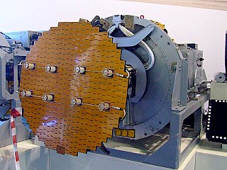
The AN/FPS-16 is a highly accurate ground-based monopulse single object tracking radar (SOTR), used extensively by the NASA crewed space program, the U.S. Air Force and the U.S. Army. The accuracy of Radar Set AN/FPS-16 is such that the position data obtained from point-source targets has azimuth and elevation angular errors of less than 0.1 milliradian and range errors of less than 5 yards (5 m) with a signal-to-noise ratio of 20 decibels or greater.
A communications satellite's transponder is the series of interconnected units that form a communications channel between the receiving and the transmitting antennas. It is mainly used in satellite communication to transfer the received signals.

Radio is the technology of communicating using radio waves. Radio waves are electromagnetic waves of frequency between 3 hertz (Hz) and 300 gigahertz (GHz). They are generated by an electronic device called a transmitter connected to an antenna which radiates oscillating electrical energy, often characterized as a wave. They can be received by other antennas connected to a radio receiver; this is the fundamental principle of radio communication. In addition to communication, radio is used for radar, radio navigation, remote control, remote sensing, and other applications.
During World War II, the German Luftwaffe relied on an increasingly diverse array of electronic communications, IFF and RDF equipment as avionics in its aircraft and also on the ground. Most of this equipment received the generic prefix FuG for Funkgerät, meaning "radio equipment". Most of the aircraft-mounted Radar equipment also used the FuG prefix. This article is a list and a description of the radio, IFF and RDF equipment.
A radio science subsystem (RSS) is a subsystem placed on board a spacecraft for radio science purposes.

The Unified S-band (USB) system is a tracking and communication system developed for the Apollo program by NASA and the Jet Propulsion Laboratory (JPL). It operated in the S band portion of the microwave spectrum, unifying voice communications, television, telemetry, command, tracking and ranging into a single system to save size and weight and simplify operations. The USB ground network was managed by the Goddard Space Flight Center (GSFC). Commercial contractors included Collins Radio, Blaw-Knox, Motorola and Energy Systems.
An emergency locator beacon is a radio beacon, a portable battery powered radio transmitter, used to locate airplanes, vessels, and persons in distress and in need of immediate rescue. Various types of emergency locator beacons are carried by aircraft, ships, vehicles, hikers and cross-country skiers. In case of an emergency, such as the aircraft crashing, the ship sinking, or a hiker becoming lost, the transmitter is deployed and begins to transmit a continuous radio signal, which is used by search and rescue teams to quickly find the emergency and render aid. The purpose of all emergency locator beacons is to help rescuers find survivors within the so-called "golden day", the first 24 hours following a traumatic event, during which the majority of survivors can usually be saved.

Explorer 29, also called GEOS 1 or GEOS A, acronym to Geodetic Earth Orbiting Satellite, was a NASA satellite launched as part of the Explorer program, being the first of the two satellites GEOS. Explorer 29 was launched on 6 November 1965 from Cape Canaveral, Florida, with a Thor-Delta E launch vehicle.
Explorer 36 was a NASA satellite launched as part of the Explorer program, being the second of the two satellites GEOS. Explorer 36 was launched on 11 January 1968 from Vandenberg Air Force Base, with Thor-Delta E1 launch vehicle.

