Orthomode transducer

Last updated
Orthomode transducer, VSAT Ku band Orthomode-transducer 01.jpg
Orthomode transducer, VSAT Ku band
Outdoor unit, includes feed horn, OMT, LNB and BUC ODU 03.jpg
Outdoor unit, includes feed horn, OMT, LNB and BUC
Orthomode transducer (Portenseigne, France) Orthogonal Mode Transduceur.jpg
Orthomode transducer (Portenseigne, France)
Orthomode transducer, vertical and horizontal polarity OMT 02.jpg
Orthomode transducer, vertical and horizontal polarity
Antenna side of OMT OMT Polarisation Circuleur Feed-Horn.jpg
Antenna side of OMT

An orthomode transducer (OMT) is a waveguide component that is commonly referred to as a polarisation duplexer. Orthomode is a contraction of orthogonal mode. Orthomode transducers serve either to combine or to separate two orthogonally polarized microwave signal paths. [1] One of the paths forms the uplink, which is transmitted over the same waveguide as the received signal path, or downlink path. Such a device may be part of a very small aperture terminal (VSAT) antenna feed or a terrestrial microwave radio feed; for example, OMTs are often used with a feed horn to isolate orthogonal polarizations of a signal and to transfer transmit and receive signals to different ports. [2]

Contents

VSAT and satellite Earth station applications

For VSAT modems the transmission and reception paths are at 90° to each other, or in other words, the signals are orthogonally polarized with respect to each other. This orthogonal shift between the two signal paths provides approximately an isolation of 40 dB in the Ku band and Ka band radio frequency bands.

Hence this device serves in an essential role as the junction element of the outdoor unit (ODU) of a VSAT modem. It protects the receiver front-end element (the low-noise block downconverter, LNB) from burn-out by the power of the output signal generated by the block up converter (BUC). The BUC is also connected to the feed horn through a wave guide port of the OMT junction device.

Orthomode transducers are used in dual-polarized VSATs, in sparsely populated areas, radar antennas, radiometers, and communications links. They are usually connected to the antenna's down converter or LNB and to the high-power amplifier (HPA), attached to a transmitting antenna.

When the transmitted and received radio signal to and from the antenna have two different polarizations (horizontal and vertical), they are said to be orthogonal. This means that the modulation planes of the two radio signal waves are at 90 degrees to each other. The OMT device is used to separate two equal frequency signals, but different polarizations, of high and low signal power. Protective separation is essential as the transmitter unit would seriously damage the very sensitive low micro-voltage (µV), front-end receiver amplifier unit at the antenna.

The transmission signal of the up-link, of relatively high power (1, 2, or 5 watts for common VSAT equipment) originating from BUC and the very low power received signal power (in the order of µV) coming from the antenna to the LNB receiver unit, in this case are at an angle of 90° relative to each other, are both coupled together at the feed-horn focal-point of the parabolic antenna. The device that unites both up-link and down-link paths, which are at 90° to each other is the OMT.

In the VSAT Ku band of operation case, a typical OMT provides a -40 dB isolation between each of the connected radio ports to the feed horn that faces the parabolic dish reflector (-40 dB means that only 0.01% of the transmitter's output power is cross-fed into the receiver's wave guide port). The port facing the parabolic reflector of the antenna is a circular polarizing port so that horizontal and vertical polarity coupling of inbound and outbound radio signal is easily achieved.

The 40 dB isolation provides essential protection to the very sensitive receiver amplifier against burn out from the relatively high-power signal of the transmitter unit. Further isolation may be obtained by means of selective radio frequency filtering to achieve an isolation of -100 dB (-100 dB means that only a 10−10 fraction of the transmitter's output power is cross-fed into the wave guide port of the receiver).

The second image demonstrates two types of outdoor units, a 1-watt Hughes unit and a composite configuration of a 2-watt BUC/OMT/LNB Andrew, Swedish Microwave units.

The following images show a Portenseigne & Hirschmann Ku band configuration, that highlights the horizontal the vertical, and circular polarized wave-guide ports that join to the feed-horn, the LNB or BUC elements of an outdoor unit.

An ortho-mode transducer is also a component commonly found on high capacity terrestrial microwave radio links. In this arrangement, two parabolic reflector dishes operate in a point to point microwave radio path (4 GHz to 85 GHz) with four radios, two mounted on each end. On each dish a T-shaped ortho-mode transducer is mounted at the rear of the feed, separating the signal from the feed into two separate radios, one operating in the horizontal polarity, and the other in the vertical polarity. This arrangement is used to increase the aggregate data throughput between two dishes on a point to point microwave path, or for fault-tolerance redundancy. Certain types of outdoor microwave radios have integrated orthomode transducers and operate in both polarities from a single radio unit, performing cross-polarization interference cancellation (XPIC) within the radio unit itself. Alternatively, the orthomode transducer may be built into the antenna, and allow connection of separate radios, or separate ports of the same radio, to the antenna.

CableFree 2+0 XPIC Microwave Link showing OMT and two ODUs connected to H & V polarity ports CableFree 2+0 HCR Microwave Link.jpg
CableFree 2+0 XPIC Microwave Link showing OMT and two ODUs connected to H & V polarity ports

Characterization

An ortho-mode transducer can be modelled as a 4-port device, 2 of these (H and V) representing the single-polarization ports and the remaining (h, v) embodied by the degenerate modes in the dual-polarized port.

The scattering parameters can be gathered in a 4×4 scattering matrix , which is symmetrical for a reciprocal OMT (i.e. not including circulators, isolators or active components), thus leaving 10 independent terms for a general lossy device:

Of these:

An ideal OMT exhibits perfect matching (null terms on the diagonal), unitary direct transmission terms and infinite XPD and isolation (null corresponding scattering parameters):

Characterization of a manufactured OMT (considered the device under test, DUT) is usually a delicate matter for both mechanical and theoretical reasons.

Conceptually, if an ideal OMT is available as part of the measurement setup, often named "golden sample", its dual-polarized port can be connected to its counterpart on the DUT, resulting in a 4-port equivalent device with 4 single-polarization ports. The ideal OMT splits the two polarizations at the dual-polarized port into two standard single-polarized ports and such arrangement allows the direct measurement of all the scattering parameters of the DUT (either by using a 4-port vector network analyzer (VNA) or a 2-port one with 2 single-polarized loads used in several combinations).

Such ideal setup is only prone to mechanical uncertainties related to the physical placement and alignment of the dual-polarized ports. A simple misalignment angle introduces an artificial path from each polarization to the opposite proportional to . The phasorial combination of the leakage (or ) due to the XPDs of DUT and this artificial loss is the actual external measured quantity. If, by proper phase recombination, the two contributions tend to cancel each other, the actual measured XPD can increase to infinity (possible only if ), thus resulting in a huge estimation error.

Depending on the expected XPD of the DUT, mechanical countermeasures should be introduced to guarantee that the artificial measurement uncertainty can be neglected.

Any deviation from this ideal setup, however, introduces errors and uncertainties.

If a dual-polarization matched load is available in place of the ideal OMT, this allows 2×2 measurements from the single-polarization ports, yielding only 2 of the reflection terms ( and ) and one IPI (). Other measurements aimed at gaining estimations of the other scattering parameters of the DUT involve the dual-polarized port and require additional components, such as dual-polarized to single-polarized transitions or tapers, which are often not matched on at least one of the two polarizations: this creates undesired reflections which propagate through the OMT and combine at the VNA ports thus preventing direct measurements. These issues add to mechanical factors and enhance uncertainties in the measurement procedure.

Due to the increasing demand for high-capacity data links, the exploitation of dual-polarization has fostered research in design and characterization of OMTs to overcome the practical difficulties. The literature concerning OMT modelling and practical characterization consists of works both by academic organizations such as the National Research Council (Italy), [3] Marche Polytechnic University and European Space Agency [4] and likewise by industrial teams such as CommScope [5] and Siae Microelettronica [6] with immediate impact on products for modern dual-polarized telecommunication systems, for instance in terrestrial microwave backhauling.

See also

Related Research Articles

<span class="mw-page-title-main">Circular polarization</span> Polarization state

In electrodynamics, circular polarization of an electromagnetic wave is a polarization state in which, at each point, the electromagnetic field of the wave has a constant magnitude and is rotating at a constant rate in a plane perpendicular to the direction of the wave.

<span class="mw-page-title-main">Circulator</span> Electronic circuit in which a signal entering any port exits at the next port

In electrical engineering, a circulator is a passive, non-reciprocal three- or four-port device that only allows a microwave or radio-frequency (RF) signal to exit through the port directly after the one it entered. Optical circulators have similar behavior. Ports are where an external waveguide or transmission line, such as a microstrip line or a coaxial cable, connects to the device. For a three-port circulator, a signal applied to port 1 only comes out of port 2; a signal applied to port 2 only comes out of port 3; a signal applied to port 3 only comes out of port 1. An ideal three-port circulator thus has the following scattering matrix:

<span class="mw-page-title-main">Polarization (waves)</span> Property of waves that can oscillate with more than one orientation

Polarization is a property of transverse waves which specifies the geometrical orientation of the oscillations. In a transverse wave, the direction of the oscillation is perpendicular to the direction of motion of the wave. A simple example of a polarized transverse wave is vibrations traveling along a taut string (see image); for example, in a musical instrument like a guitar string. Depending on how the string is plucked, the vibrations can be in a vertical direction, horizontal direction, or at any angle perpendicular to the string. In contrast, in longitudinal waves, such as sound waves in a liquid or gas, the displacement of the particles in the oscillation is always in the direction of propagation, so these waves do not exhibit polarization. Transverse waves that exhibit polarization include electromagnetic waves such as light and radio waves, gravitational waves, and transverse sound waves in solids.

<span class="mw-page-title-main">Radio wave</span> Type of electromagnetic radiation

Radio waves are a type of electromagnetic radiation with the longest wavelengths in the electromagnetic spectrum, typically with frequencies of 300 gigahertz (GHz) and below. At 300 GHz, the corresponding wavelength is 1mm, which is shorter than the diameter of a grain of rice. At 30 Hz the corresponding wavelength is ~10,000 kilometers, which is longer than the radius of the Earth. Wavelength of a radio wave is inversely proportional to its frequency, because its velocity is constant. Like all electromagnetic waves, radio waves in a vacuum travel at the speed of light, and in the Earth's atmosphere at a slightly slower speed. Radio waves are generated by charged particles undergoing acceleration, such as time-varying electric currents. Naturally occurring radio waves are emitted by lightning and astronomical objects, and are part of the blackbody radiation emitted by all warm objects.

<span class="mw-page-title-main">Antenna (radio)</span> Electrical device

In radio engineering, an antenna or aerial is the interface between radio waves propagating through space and electric currents moving in metal conductors, used with a transmitter or receiver. In transmission, a radio transmitter supplies an electric current to the antenna's terminals, and the antenna radiates the energy from the current as electromagnetic waves. In reception, an antenna intercepts some of the power of a radio wave in order to produce an electric current at its terminals, that is applied to a receiver to be amplified. Antennas are essential components of all radio equipment.

<span class="mw-page-title-main">Very-small-aperture terminal</span> Satellite communication system with small dish antenna

A very-small-aperture terminal (VSAT) is a two-way satellite ground station with a dish antenna that is smaller than 3.8 meters. The majority of VSAT antennas range from 75 cm to 1.2 m. Bit rates, in most cases, range from 4 kbit/s up to 16 Mbit/s. VSATs access satellites in geosynchronous orbit or geostationary orbit to relay data from small remote Earth stations (terminals) to other terminals or master Earth station "hubs".

<span class="mw-page-title-main">Parabolic antenna</span> Type of antenna

A parabolic antenna is an antenna that uses a parabolic reflector, a curved surface with the cross-sectional shape of a parabola, to direct the radio waves. The most common form is shaped like a dish and is popularly called a dish antenna or parabolic dish. The main advantage of a parabolic antenna is that it has high directivity. It functions similarly to a searchlight or flashlight reflector to direct radio waves in a narrow beam, or receive radio waves from one particular direction only. Parabolic antennas have some of the highest gains, meaning that they can produce the narrowest beamwidths, of any antenna type. In order to achieve narrow beamwidths, the parabolic reflector must be much larger than the wavelength of the radio waves used, so parabolic antennas are used in the high frequency part of the radio spectrum, at UHF and microwave (SHF) frequencies, at which the wavelengths are small enough that conveniently sized reflectors can be used.

<span class="mw-page-title-main">Low-noise block downconverter</span> Receiving device on satellite dishes

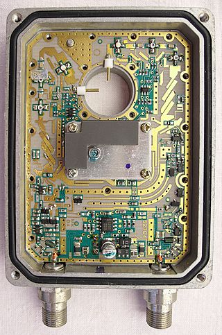
A low-noise block downconverter (LNB) is the receiving device mounted on satellite dishes used for satellite TV reception, which collects the radio waves from the dish and converts them to a signal which is sent through a cable to the receiver inside the building. Also called a low-noise block, low-noise converter (LNC), or even low-noise downconverter (LND), the device is sometimes inaccurately called a low-noise amplifier (LNA).

<span class="mw-page-title-main">Effective radiated power</span> Definition of directional radio frequency power

Effective radiated power (ERP), synonymous with equivalent radiated power, is an IEEE standardized definition of directional radio frequency (RF) power, such as that emitted by a radio transmitter. It is the total power in watts that would have to be radiated by a half-wave dipole antenna to give the same radiation intensity as the actual source antenna at a distant receiver located in the direction of the antenna's strongest beam. ERP measures the combination of the power emitted by the transmitter and the ability of the antenna to direct that power in a given direction. It is equal to the input power to the antenna multiplied by the gain of the antenna. It is used in electronics and telecommunications, particularly in broadcasting to quantify the apparent power of a broadcasting station experienced by listeners in its reception area.

<span class="mw-page-title-main">Polarimetry</span> Measurement and interpretation of the polarization of transverse waves

Polarimetry is the measurement and interpretation of the polarization of transverse waves, most notably electromagnetic waves, such as radio or light waves. Typically polarimetry is done on electromagnetic waves that have traveled through or have been reflected, refracted or diffracted by some material in order to characterize that object.

<span class="mw-page-title-main">Isotropic radiator</span>

An isotropic radiator is a theoretical point source of electromagnetic or sound waves which radiates the same intensity of radiation in all directions. It has no preferred direction of radiation. It radiates uniformly in all directions over a sphere centred on the source. Isotropic radiators are used as reference radiators with which other sources are compared, for example in determining the gain of antennas. A coherent isotropic radiator of electromagnetic waves is theoretically impossible, but incoherent radiators can be built. An isotropic sound radiator is possible because sound is a longitudinal wave.

<span class="mw-page-title-main">Network analyzer (electrical)</span> Instrument that measures the network parameters of electrical networks

A network analyzer is an instrument that measures the network parameters of electrical networks. Today, network analyzers commonly measure s–parameters because reflection and transmission of electrical networks are easy to measure at high frequencies, but there are other network parameter sets such as y-parameters, z-parameters, and h-parameters. Network analyzers are often used to characterize two-port networks such as amplifiers and filters, but they can be used on networks with an arbitrary number of ports.

Fluorescence anisotropy or fluorescence polarization is the phenomenon where the light emitted by a fluorophore has unequal intensities along different axes of polarization. Early pioneers in the field include Aleksander Jablonski, Gregorio Weber, and Andreas Albrecht. The principles of fluorescence polarization and some applications of the method are presented in Lakowicz's book.

<span class="mw-page-title-main">Vivaldi antenna</span> Type of broadband antenna

A Vivaldi antenna or Vivaldi aerial or tapered slot antenna is a co-planar broadband-antenna, which can be made from a solid piece of sheet metal, a printed circuit board, or from a dielectric plate metalized on one or both sides.

<span class="mw-page-title-main">Dual-band blade antenna</span>

A dual-band blade antenna is a type of blade antenna, a monopole whip antenna mounted on the outside of an aircraft in the form of a blade-shaped aerodynamic fairing to reduce its air drag. It is used by avionics radio communication systems. The dual band type uses a "plane and slot" design to allow efficient omni-directional coverage so that it can operate on two different radio bands.

A radio science subsystem (RSS) is a subsystem placed on board a spacecraft for radio science purposes.

<span class="mw-page-title-main">Spiral antenna</span> Type of RF antenna

A spiral antenna is a type of radio frequency antenna shaped as a spiral, first described in 1956. Archimedean spiral antennas are the most popular, while logarithmic spiral antennas are independent of frequency: the driving point impedance, radiation pattern and polarization of such antennas remain unchanged over a large bandwidth. Spiral antennas are inherently circularly polarized with low gain; antenna arrays can be used to increase the gain. Spiral antennas are reduced in size with its windings making it an extremely small structure. Lossy cavities are usually placed at the back to eliminate back lobes, because a unidirectional pattern is usually preferred in such antennas. Spiral antennas are classified into different configurations: Archimedean spiral, logarithmic spiral, square spiral, etc.

<span class="mw-page-title-main">Polarization-division multiplexing</span> Method for multiplexing signals

Polarization-division multiplexing (PDM) is a physical layer method for multiplexing signals carried on electromagnetic waves, allowing two channels of information to be transmitted on the same carrier frequency by using waves of two orthogonal polarization states. It is used in microwave links such as satellite television downlinks to double the bandwidth by using two orthogonally polarized feed antennas in satellite dishes. It is also used in fiber optic communication by transmitting separate left and right circularly polarized light beams through the same optical fiber.

<span class="mw-page-title-main">XPIC</span>

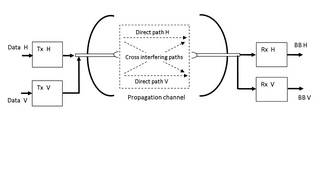
XPIC, or cross-polarization interference cancelling technology, is an algorithm to suppress mutual interference between two received streams in a Polarization-division multiplexing communication system.

<span class="mw-page-title-main">Joint Polarization Experiment</span>

The Joint Polarization Experiment (JPOLE) was a test for evaluating the performance of the WSR-88D in order to modify it to include dual polarization. This program was a joint project of the National Weather Service (NWS), the Federal Aviation Administration (FAA), and the US Air Force Meteorological Agency (AFWA), which took place from 2000-2004. It has resulted in the upgrading of the entire meteorological radar network in the United States by adding dual polarization to better determine the type of hydrometeor, and quantities that have fallen.

References

  1. "orthomode transducer". Institute for Telecommunication Sciences. 1996-08-23. Retrieved 2013-06-29.
  2. Bartlett, Mike (2010). "FAQ". SAS Ltd. Archived from the original on 2013-07-06. Retrieved 2013-06-29.
  3. Peverini, O.; Tascone, R.; Olivieri, A.; Baralis, M.; Orta, R.; Virone, G. (2003). "A microwave measurement procedure for a full characterization of ortho-mode transducers". IEEE Transactions on Microwave Theory and Techniques. 51 (4): 1207–1213. Bibcode:2003ITMTT..51.1207P. doi:10.1109/TMTT.2003.809629.
  4. Morini, A.; Guglielmi, M.; Farina, M. (2013). "A technique for the measurement of the generalized scattering matrix of overmoded waveguide devices". IEEE Transactions on Microwave Theory and Techniques. 61 (7): 2705–2714. Bibcode:2013ITMTT..61.2705M. doi:10.1109/TMTT.2013.2265683. S2CID   15432629.
  5. Syme, Jim (26 August 2014). "Back to Basics in Microwave Systems: Cross-Polar Discrimination" . Retrieved 6 December 2016.
  6. Oldoni, Matteo; Tresoldi, Dario (2016). Cheap Method for Accurate Characterization of Orthomode Transducers. IEEE Microwave Symposium Digest (MTT). doi:10.1109/MWSYM.2016.7538836.