In electronics and telecommunications, modulation is the process of varying one or more properties of a periodic waveform, called the carrier signal, with a separate signal called the modulation signal that typically contains information to be transmitted. For example, the modulation signal might be an audio signal representing sound from a microphone, a video signal representing moving images from a video camera, or a digital signal representing a sequence of binary digits, a bitstream from a computer.

In telecommunications, orthogonal frequency-division multiplexing (OFDM) is a type of digital transmission used in digital modulation for encoding digital (binary) data on multiple carrier frequencies. OFDM has developed into a popular scheme for wideband digital communication, used in applications such as digital television and audio broadcasting, DSL internet access, wireless networks, power line networks, and 4G/5G mobile communications.

Coaxial cable, or coax, is a type of electrical cable consisting of an inner conductor surrounded by a concentric conducting shield, with the two separated by a dielectric ; many coaxial cables also have a protective outer sheath or jacket. The term coaxial refers to the inner conductor and the outer shield sharing a geometric axis.
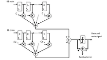
An adaptive filter is a system with a linear filter that has a transfer function controlled by variable parameters and a means to adjust those parameters according to an optimization algorithm. Because of the complexity of the optimization algorithms, almost all adaptive filters are digital filters. Adaptive filters are required for some applications because some parameters of the desired processing operation are not known in advance or are changing. The closed loop adaptive filter uses feedback in the form of an error signal to refine its transfer function.

A parabolic antenna is an antenna that uses a parabolic reflector, a curved surface with the cross-sectional shape of a parabola, to direct the radio waves. The most common form is shaped like a dish and is popularly called a dish antenna or parabolic dish. The main advantage of a parabolic antenna is that it has high directivity. It functions similarly to a searchlight or flashlight reflector to direct radio waves in a narrow beam, or receive radio waves from one particular direction only. Parabolic antennas have some of the highest gains, meaning that they can produce the narrowest beamwidths, of any antenna type. In order to achieve narrow beamwidths, the parabolic reflector must be much larger than the wavelength of the radio waves used, so parabolic antennas are used in the high frequency part of the radio spectrum, at UHF and microwave (SHF) frequencies, at which the wavelengths are small enough that conveniently sized reflectors can be used.

Coding theory is the study of the properties of codes and their respective fitness for specific applications. Codes are used for data compression, cryptography, error detection and correction, data transmission and data storage. Codes are studied by various scientific disciplines—such as information theory, electrical engineering, mathematics, linguistics, and computer science—for the purpose of designing efficient and reliable data transmission methods. This typically involves the removal of redundancy and the correction or detection of errors in the transmitted data.

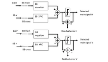
An adaptive equalizer is an equalizer that automatically adapts to time-varying properties of the communication channel. It is frequently used with coherent modulations such as phase-shift keying, mitigating the effects of multipath propagation and Doppler spreading.

An orthomode transducer (OMT) is a waveguide component that is commonly referred to as a polarisation duplexer. Orthomode is a contraction of orthogonal mode. Orthomode transducers serve either to combine or to separate two orthogonally polarized microwave signal paths. One of the paths forms the uplink, which is transmitted over the same waveguide as the received signal path, or downlink path. Such a device may be part of a very small aperture terminal (VSAT) antenna feed or a terrestrial microwave radio feed; for example, OMTs are often used with a feed horn to isolate orthogonal polarizations of a signal and to transfer transmit and receive signals to different ports.
Affine arithmetic (AA) is a model for self-validated numerical analysis. In AA, the quantities of interest are represented as affine combinations of certain primitive variables, which stand for sources of uncertainty in the data or approximations made during the computation.
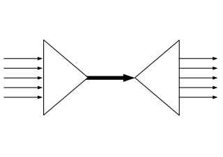
Spatial multiplexing or space-division multiplexing is a multiplexing technique in MIMO wireless communication, fiber-optic communication and other communications technologies used to transmit independent channels separated in space.
Precoding is a generalization of beamforming to support multi-stream transmission in multi-antenna wireless communications. In conventional single-stream beamforming, the same signal is emitted from each of the transmit antennas with appropriate weighting such that the signal power is maximized at the receiver output. When the receiver has multiple antennas, single-stream beamforming cannot simultaneously maximize the signal level at all of the receive antennas. In order to maximize the throughput in multiple receive antenna systems, multi-stream transmission is generally required.
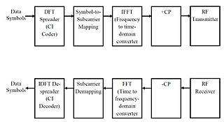
Carrier Interferometry(CI) is a spread spectrum scheme designed to be used in an Orthogonal Frequency-Division Multiplexing (OFDM) communication system for multiplexing and multiple access, enabling the system to support multiple users at the same time over the same frequency band.
Flexoelectricity is a property of a dielectric material where there is coupling between electrical polarization and a strain gradient. Flexoelectricity is closely related to piezoelectricity, but while piezoelectricity refers to polarization due to uniform strain, flexoelectricity refers specifically to polarization due to strain that changes from point to point in the material. This nonuniform strain breaks centrosymmetry, meaning that unlike in piezoelectricity, flexoelectric effects occur in both centrosymmetric and asymmetric crystal structures. Flexoelectricity is not the same as Ferroelasticity. Flexoelectricity plays a critical role in explaining many interesting electromechanical behaviors in hard crystalline materials and core mechanoelectric transduction phenomena in soft biomaterials. Most excitingly, flexoelectricity is a size-dependent effect that becomes more significant in nanoscale systems, such as crack tips.
In digital communications, a turbo equalizer is a type of receiver used to receive a message corrupted by a communication channel with intersymbol interference (ISI). It approaches the performance of a maximum a posteriori (MAP) receiver via iterative message passing between a soft-in soft-out (SISO) equalizer and a SISO decoder. It is related to turbo codes in that a turbo equalizer may be considered a type of iterative decoder if the channel is viewed as a non-redundant convolutional code. The turbo equalizer is different from classic a turbo-like code, however, in that the 'channel code' adds no redundancy and therefore can only be used to remove non-gaussian noise.

An antenna array is a set of multiple connected antennas which work together as a single antenna, to transmit or receive radio waves. The individual antennas are usually connected to a single receiver or transmitter by feedlines that feed the power to the elements in a specific phase relationship. The radio waves radiated by each individual antenna combine and superpose, adding together to enhance the power radiated in desired directions, and cancelling to reduce the power radiated in other directions. Similarly, when used for receiving, the separate radio frequency currents from the individual antennas combine in the receiver with the correct phase relationship to enhance signals received from the desired directions and cancel signals from undesired directions. More sophisticated array antennas may have multiple transmitter or receiver modules, each connected to a separate antenna element or group of elements.
The spin angular momentum of light (SAM) is the component of angular momentum of light that is associated with the quantum spin and the rotation between the polarization degrees of freedom of the photon.

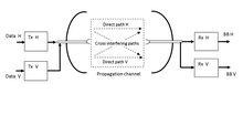
Polarization-division multiplexing (PDM) is a physical layer method for multiplexing signals carried on electromagnetic waves, allowing two channels of information to be transmitted on the same carrier frequency by using waves of two orthogonal polarization states. It is used in microwave links such as satellite television downlinks to double the bandwidth by using two orthogonally polarized feed antennas in satellite dishes. It is also used in fiber optic communication by transmitting separate left and right circularly polarized light beams through the same optical fiber.
Carrier frequency offset (CFO) is one of many non-ideal conditions that may affect in baseband receiver design. In designing a baseband receiver, we should notice not only the degradation invoked by non-ideal channel and noise, we should also regard RF and analog parts as the main consideration. Those non-idealities include sampling clock offset, IQ imbalance, power amplifier, phase noise and carrier frequency offset nonlinearity.
IQ imbalance is a performance-limiting issue in the design of a class of radio receivers known as direct conversion receivers. These translate the received radio frequency signal directly from the carrier frequency to baseband using a single mixing stage.
Non-orthogonal frequency-division multiplexing (N-OFDM) is a method of encoding digital data on multiple carrier frequencies with non-orthogonal intervals between frequency of sub-carriers. N-OFDM signals can be used in communication and radar systems.
