Overspeed

Last updated

Overspeed is a condition in which an engine is allowed or forced to turn beyond its design limit. The consequences of running an engine too fast vary by engine type and model and depend upon several factors, the most important of which are the duration of the overspeed and the speed attained. With some engines, a momentary overspeed can result in greatly reduced engine life or catastrophic failure. [1] The speed of an engine is typically measured in revolutions per minute (rpm). [2] [ citation needed ]

Contents

Examples of overspeed

Overspeed protection

Sometimes a regulator or governor is fitted to make engine overspeed impossible or less likely. For example:

Different overspeed occurrences and prevention

Internal combustion engines

An excerpt presented by the San Francisco Maritime National Park Association illustrates the types of overspeed systems with governor and engine control. [4] Overspeed governors are either centrifugal or hydraulic. [4] Centrifugal governors depend on the revolving force created by its own weight. [4] Hydraulic governors use the centrifugal force but drive a medium to accomplish the same task. [4] The overspeed governor is implemented on most marine diesel engines. [4] The governor is a safety measure that acts when the engine is approaching overspeed and will trip the engine off if the regulator governor fails. [4] It trips off the engine by cutting off fuel injection by having the centrifugal force act on levers linked to the governor collar. [4]

Turbines

Overspeeds for power plant turbines can be catastrophic, resulting in failure due to the turbines' shafts and blades being off balance and potentially throwing their blades and other metal parts at very high speeds. [5] Different safeguards exist, which include a mechanical and electrical protection system. [6]

Mechanical overspeed protection is in the form of sensors. [6] The system relies on the centripetal force of the shaft, a spring, and a weight. [6] At the designed point of overspeed, the balance point of the weight is shifted, causing the lever to release a valve that makes the trip oil header to lose pressure due to draining. [6] This loss of oil affects the pressure, and moves a trip mechanism to then trip the system off. [6]

An electrical overspeed detection system involves a gear with teeth and probes. [6] These probes detect how fast the teeth are moving, and if they are moving beyond the designated rpm, it relays that to the logic solver (overspeed detection). The logic solver trips the system by sending the overspeed to the trip relay, which is connected to a solenoid-operated valve. [6]

Mechanical vs. electrical governors on turbines

In turbines and many other mechanical devices used for power generation, it is critical that the response times for overspeed prevention systems be as precise as possible. [7] If the response is off by even a fraction of a second, it can lead to turbines and its driven load (i.e. compressor, generator, pump, etc..) suffering catastrophic damage and put people at risk. [7]

Mechanical

Mechanical overspeed systems on turbines rely on an equilibrium between the centripetal force of the rotating shaft imparted on a weight attached to the end of a turbine blade. [7] At the specified trip point, this weight makes physical contact with a lever that releases the trip oil header, which directly moves a trip bolt and/or a hydraulic circuit to activate stop valves to close. [7] Because the contact with the lever occurs over a relatively limited angle, there is a maximum trip response time of 15 ms (i.e. 0.015 sec). [7] The issue with these devices has less to do with response time as it does with response latency and variability in the trip point due to systems sticking. [7] Some systems add two trip bolts for redundancy, which enables response latency to be reduced by half. [7]

Electrical

Electrical overspeed systems on turbines rely on a multitude of probes that sense speed through measuring the passages of the teeth of a spur gear. [7] Using a digital logic solver, the overspeed system determines the propeller shaft rpm given the ratio of the gear to the shaft. [7] If the shaft rpm is too high, it outputs a trip command which de-energizes a trip relay. [7] Overspeed response varies from system to system, so it is key to check the original equipment manufacturer's specification to set the Overspeed trip time accordingly. [7] Typically, unless specified otherwise, the response time to change the output relay will be 40 ms. [7] This time includes the time required for the probes to detect speed, compare it to an overspeed set-point, calculate results, and finally output the trip command. [7]

Overview of overspeed detection system

When configuring, testing, and running any overspeed systems on turbines or diesel engines, one factor considered is timing. [4] This is because the response to overspeed is usually too fast for people to notice.

There is a strong argument to instrument the trip systems in such a way that the total system response can be measured. This way during a test a change in the response could indicate a degradation that might compromise system protection or point out a failing component.

Scott, 2009, p.161 [6]

The responsibility of calibrating the correct overspeed response for a specific system falls on the manufacturer. However, variability is always present, and it is important for the owner/operator to understand the system in the event of maintenance, replacement, or retrofitting of outdated or worn out parts. [6] After overspeed has occurred, it is essential to check all machinery parts for stress. [8] The first place to start for impulse turbines is the rotor. [8] At the rotor, there are balance holes [9] that equalise the pressure difference between turbines, and if warped, would require the replacement of the entire rotor. [8]

See also

Related Research Articles

<span class="mw-page-title-main">Steam engine</span> Engine that uses steam to perform mechanical work

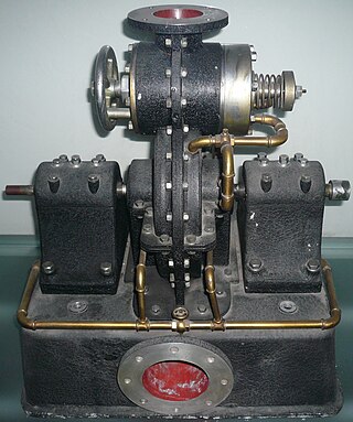
A steam engine is a heat engine that performs mechanical work using steam as its working fluid. The steam engine uses the force produced by steam pressure to push a piston back and forth inside a cylinder. This pushing force can be transformed, by a connecting rod and crank, into rotational force for work. The term "steam engine" is most commonly applied to reciprocating engines as just described, although some authorities have also referred to the steam turbine and devices such as Hero's aeolipile as "steam engines". The essential feature of steam engines is that they are external combustion engines, where the working fluid is separated from the combustion products. The ideal thermodynamic cycle used to analyze this process is called the Rankine cycle. In general usage, the term steam engine can refer to either complete steam plants, such as railway steam locomotives and portable engines, or may refer to the piston or turbine machinery alone, as in the beam engine and stationary steam engine.
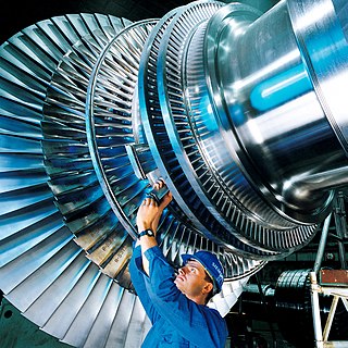
<span class="mw-page-title-main">Steam turbine</span> Machine that uses steam to rotate a shaft

A steam turbine is a machine that extracts thermal energy from pressurized steam and uses it to do mechanical work on a rotating output shaft. Its modern manifestation was invented by Charles Parsons in 1884. Fabrication of a modern steam turbine involves advanced metalwork to form high-grade steel alloys into precision parts using technologies that first became available in the 20th century; continued advances in durability and efficiency of steam turbines remains central to the energy economics of the 21st century.

<span class="mw-page-title-main">Tesla turbine</span> Bladeless centripetal flow turbine

The Tesla turbine is a bladeless centripetal flow turbine invented by Nikola Tesla in 1913. It functions as nozzles apply a moving fluid to the edges of a set of discs. The engine uses smooth discs rotating in a chamber to generate rotational movement due to the momentum exchange between the fluid and the discs. The discs are arranged in an orientation similar to a stack of CDs on a pole.

<span class="mw-page-title-main">Turbocharger</span> Exhaust-powered forced-induction device for engines

In an internal combustion engine, a turbocharger is a forced induction device that is powered by the flow of exhaust gases. It uses this energy to compress the intake air, forcing more air into the engine in order to produce more power for a given displacement.

<span class="mw-page-title-main">Turboprop</span> Turbine engine driving an aircraft propeller

A turboprop is a turbine engine that drives an aircraft propeller.
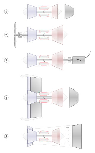
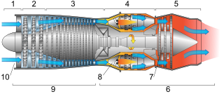
<span class="mw-page-title-main">Gas turbine</span> Type of internal and continuous combustion engine

A gas turbine, gas turbine engine, or also known by its old name internal combustion turbine, is a type of continuous flow internal combustion engine. The main parts common to all gas turbine engines form the power-producing part and are, in the direction of flow:

<span class="mw-page-title-main">Turbofan</span> Airbreathing jet engine designed to provide thrust by driving a fan

A turbofan or fanjet is a type of airbreathing jet engine that is widely used in aircraft propulsion. The word "turbofan" is a combination of the preceding generation engine technology of the turbojet, and a reference to the additional fan stage added. It consists of a gas turbine engine which achieves mechanical energy from combustion, and a ducted fan that uses the mechanical energy from the gas turbine to force air rearwards. Thus, whereas all the air taken in by a turbojet passes through the combustion chamber and turbines, in a turbofan some of that air bypasses these components. A turbofan thus can be thought of as a turbojet being used to drive a ducted fan, with both of these contributing to the thrust.

<span class="mw-page-title-main">Aircraft engine controls</span>

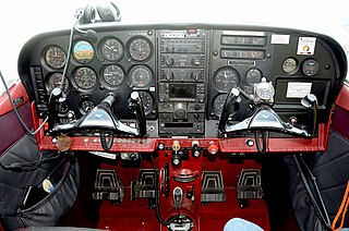
Aircraft engine controls provide a means for the pilot to control and monitor the operation of the aircraft's powerplant. This article describes controls used with a basic internal-combustion engine driving a propeller. Some optional or more advanced configurations are described at the end of the article. Jet turbine engines use different operating principles and have their own sets of controls and sensors.

A governor, or speed limiter or controller, is a device used to measure and regulate the speed of a machine, such as an engine.

<span class="mw-page-title-main">Ducted fan</span> Air moving arrangement

In aeronautics, a ducted fan is a thrust-generating mechanical fan or propeller mounted within a cylindrical duct or shroud. Other terms include ducted propeller or shrouded propeller. When used in vertical takeoff and landing (VTOL) applications it is also known as a shrouded rotor.

<span class="mw-page-title-main">Pratt & Whitney Canada PT6</span> Turboprop aircraft engine family by Pratt & Whitney Canada

The Pratt & Whitney Canada PT6 is a turboprop aircraft engine produced by Pratt & Whitney Canada. Its design was started in 1958, it first ran in February 1960, first flew on 30 May 1961, entered service in 1964, and has been continuously updated since. The PT6 consists of two basic sections: a gas generator with accessory gearbox, and a free-power turbine with reduction gearbox. In aircraft, the engine is often mounted "backwards," with the intake at the rear and the exhaust at the front, so that the turbine is directly connected to the propeller. Many variants of the PT6 have been produced, not only as turboprops but also as turboshaft engines for helicopters, land vehicles, hovercraft, and boats; as auxiliary power units; and for industrial uses. By November 2015, 51,000 had been produced, which had logged 400 million flight hours from 1963 to 2016. It is known for its reliability, with an in-flight shutdown rate of 1 per 651,126 hours in 2016. The PT6A turboprop engine covers the power range between 580 and 1,940 shp, while the PT6B/C are turboshaft variants for helicopters.

<span class="mw-page-title-main">Helicopter flight controls</span> Instruments used in helicopter flight

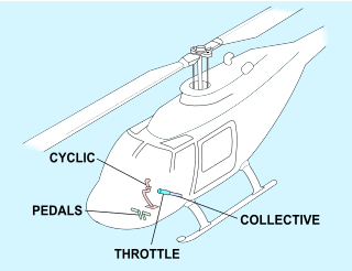
Helicopter flight controls are used to achieve and maintain controlled aerodynamic helicopter flight. Changes to the aircraft flight control system transmit mechanically to the rotor, producing aerodynamic effects on the rotor blades that make the helicopter move in a desired way. To tilt forward and back (pitch) or sideways (roll) requires that the controls alter the angle of attack of the main rotor blades cyclically during rotation, creating differing amounts of lift at different points in the cycle. To increase or decrease overall lift requires that the controls alter the angle of attack for all blades collectively by equal amounts at the same time, resulting in ascent, descent, acceleration and deceleration.

A compressor map is a chart which shows the performance of a turbomachinery compressor. This type of compressor is used in gas turbine engines, for supercharging reciprocating engines and for industrial processes, where it is known as a dynamic compressor. A map is created from compressor rig test results or predicted by a special computer program. Alternatively the map of a similar compressor can be suitably scaled. This article is an overview of compressor maps and their different applications and also has detailed explanations of maps for a fan and intermediate and high-pressure compressors from a three-shaft aero-engine as specific examples.

<span class="mw-page-title-main">Variable-pitch propeller (aeronautics)</span> Propeller with blades that can be rotated to control their pitch while in use

In aeronautics, a variable-pitch propeller is a type of propeller (airscrew) with blades that can be rotated around their long axis to change the blade pitch. A controllable-pitch propeller is one where the pitch is controlled manually by the pilot. Alternatively, a constant-speed propeller is one where the pilot sets the desired engine speed (RPM), and the blade pitch is controlled automatically without the pilot's intervention so that the rotational speed remains constant. The device which controls the propeller pitch and thus speed is called a propeller governor or constant speed unit.

<span class="mw-page-title-main">Marine propulsion</span> Systems for generating thrust for ships and boats on water

Marine propulsion is the mechanism or system used to generate thrust to move a watercraft through water. While paddles and sails are still used on some smaller boats, most modern ships are propelled by mechanical systems consisting of an electric motor or internal combustion engine driving a propeller, or less frequently, in pump-jets, an impeller. Marine engineering is the discipline concerned with the engineering design process of marine propulsion systems.

<span class="mw-page-title-main">Components of jet engines</span> Brief description of components needed for jet engines

This article briefly describes the components and systems found in jet engines.

An airbreathing jet engine is a jet engine in which the exhaust gas which supplies jet propulsion is atmospheric air, which is taken in, compressed, heated, and expanded back to atmospheric pressure through a propelling nozzle. Compression may be provided by a gas turbine, as in the original turbojet and newer turbofan, or arise solely from the ram pressure of the vehicle's velocity, as with the ramjet and pulsejet.

<span class="mw-page-title-main">Internal combustion engine</span> Engine in which the combustion of a fuel occurs with an oxidizer in a combustion chamber

An internal combustion engine is a heat engine in which the combustion of a fuel occurs with an oxidizer in a combustion chamber that is an integral part of the working fluid flow circuit. In an internal combustion engine, the expansion of the high-temperature and high-pressure gases produced by combustion applies direct force to some component of the engine. The force is typically applied to pistons, turbine blades, a rotor, or a nozzle. This force moves the component over a distance, transforming chemical energy into kinetic energy which is used to propel, move or power whatever the engine is attached to.

<span class="mw-page-title-main">Free-turbine turboshaft</span>

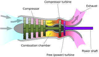
A free-turbine turboshaft is a form of turboshaft or turboprop gas turbine engine where the power is extracted from the exhaust stream of a gas turbine by an independent turbine, downstream of the gas turbine. The power turbine is not mechanically connected to the turbines that drive the compressors, hence the term "free", referring to the independence of the power output shaft. This is opposed to the power being extracted from the turbine/compressor shaft via a gearbox.

<span class="mw-page-title-main">Pakistan International Airlines Flight 661</span> Aviation accident in Havelian, Pakistan

Pakistan International Airlines Flight 661 was a Pakistani domestic passenger flight from Chitral to Islamabad, operated by Pakistan's flag carrier Pakistan International Airlines. On 7 December 2016, the aircraft serving the route, an ATR 42-500 twin-turboprop, lost control and crashed near Havelian following an engine failure. All 47 people on board died, including singer-turned-preacher and entrepreneur Junaid Jamshed, and the Deputy Commissioner of the District of Chitral.

References

  1. || Google Patents: Engine overspeed shutdown systems and methods
  2. || OBP: ISO 7000 — Graphical symbols for use on equipment
  3. AMOT Products.
  4. 1 2 3 4 5 6 7 8 "Submarine Main Propulsion Diesels - Chapter 10". maritime.org. Retrieved 2019-04-02.
  5. Perez, R. X. (2016). Operators guide to general purpose steam turbines: An overview of operating principles, construction, best practices, and troubleshooting. Hoboken, NJ: John Wiley & Sons.
  6. 1 2 3 4 5 6 7 8 9 Taylor, Scott (June 2009). "Turbine Overspeed Systems and Required Response" (PDF). Semantic scholat. S2CID   15076138. Archived from the original (PDF) on 2019-03-04. Retrieved March 14, 2019.
  7. 1 2 3 4 5 6 7 8 9 10 11 12 13 Smith, Sheldon S.; Taylor, Scott L. (2009). "Turbine Overspeed Systems And Required Response Times". Turbomachinery and Pump Symposia. doi:10.21423/R19W7P.
  8. 1 2 3 National Marine Engineers' Beneficial Association (U.S.). District 1. Modern marine engineering. MEBA. OCLC   28049257.{{cite book}}: CS1 maint: numeric names: authors list (link)
  9. Mrózek, Lukáš; Tajč, Ladislav; Hoznedl, Michal; Miczán, Martin (28 March 2016). Application of the balancing holes on the turbine stage discs with higher root reaction (PDF). EFM15 – Experimental Fluid Mechanics 2015. EPJ Web of Conferences. Vol. 114. doi:10.1051/epjconf/201611402080.