
An electrical network is an interconnection of electrical components or a model of such an interconnection, consisting of electrical elements. An electrical circuit is a network consisting of a closed loop, giving a return path for the current. Thus all circuits are networks, but not all networks are circuits. Linear electrical networks, a special type consisting only of sources, linear lumped elements, and linear distributed elements, have the property that signals are linearly superimposable. They are thus more easily analyzed, using powerful frequency domain methods such as Laplace transforms, to determine DC response, AC response, and transient response.
In electrical engineering, electrical elements are conceptual abstractions representing idealized electrical components, such as resistors, capacitors, and inductors, used in the analysis of electrical networks. All electrical networks can be analyzed as multiple electrical elements interconnected by wires. Where the elements roughly correspond to real components, the representation can be in the form of a schematic diagram or circuit diagram. This is called a lumped-element circuit model. In other cases, infinitesimal elements are used to model the network in a distributed-element model.
In electrical engineering, the distributed-element model or transmission-line model of electrical circuits assumes that the attributes of the circuit are distributed continuously throughout the material of the circuit. This is in contrast to the more common lumped-element model, which assumes that these values are lumped into electrical components that are joined by perfectly conducting wires. In the distributed-element model, each circuit element is infinitesimally small, and the wires connecting elements are not assumed to be perfect conductors; that is, they have impedance. Unlike the lumped-element model, it assumes nonuniform current along each branch and nonuniform voltage along each wire.

A gyrator is a passive, linear, lossless, two-port electrical network element proposed in 1948 by Bernard D. H. Tellegen as a hypothetical fifth linear element after the resistor, capacitor, inductor and ideal transformer. Unlike the four conventional elements, the gyrator is non-reciprocal. Gyrators permit network realizations of two-(or-more)-port devices which cannot be realized with just the four conventional elements. In particular, gyrators make possible network realizations of isolators and circulators. Gyrators do not however change the range of one-port devices that can be realized. Although the gyrator was conceived as a fifth linear element, its adoption makes both the ideal transformer and either the capacitor or inductor redundant. Thus the number of necessary linear elements is in fact reduced to three. Circuits that function as gyrators can be built with transistors and op-amps using feedback.
Capacitors and inductors as used in electric circuits are not ideal components with only capacitance or inductance. However, they can be treated, to a very good degree of approximation, as being ideal capacitors and inductors in series with a resistance; this resistance is defined as the equivalent series resistance (ESR). If not otherwise specified, the ESR is always an AC resistance, which means it is measured at specified frequencies, 100 kHz for switched-mode power supply components, 120 Hz for linear power-supply components, and at its self-resonant frequency for general-application components. Additionally, audio components may report a "Q factor", incorporating ESR among other things, at 1000 Hz.
A Colpitts oscillator, invented in 1918 by Canadian-American engineer Edwin H. Colpitts using vacuum tubes, is one of a number of designs for LC oscillators, electronic oscillators that use a combination of inductors (L) and capacitors (C) to produce an oscillation at a certain frequency. The distinguishing feature of the Colpitts oscillator is that the feedback for the active device is taken from a voltage divider made of two capacitors in series across the inductor.

Electronic filters are a type of signal processing filter in the form of electrical circuits. This article covers those filters consisting of lumped electronic components, as opposed to distributed-element filters. That is, using components and interconnections that, in analysis, can be considered to exist at a single point. These components can be in discrete packages or part of an integrated circuit.
Equivalent series inductance (ESL) is an effective inductance that is used to describe the inductive part of the impedance of certain electrical components.
In microwave and radio-frequency engineering, a stub or resonant stub is a length of transmission line or waveguide that is connected at one end only. The free end of the stub is either left open-circuit, or short-circuited. Neglecting transmission line losses, the input impedance of the stub is purely reactive; either capacitive or inductive, depending on the electrical length of the stub, and on whether it is open or short circuit. Stubs may thus function as capacitors, inductors and resonant circuits at radio frequencies.

Electrical resonance occurs in an electric circuit at a particular resonant frequency when the impedances or admittances of circuit elements cancel each other. In some circuits, this happens when the impedance between the input and output of the circuit is almost zero and the transfer function is close to one.

Parasitic capacitance or stray capacitance is the unavoidable and usually unwanted capacitance that exists between the parts of an electronic component or circuit simply because of their proximity to each other. When two electrical conductors at different voltages are close together, the electric field between them causes electric charge to be stored on them; this effect is capacitance.

A test probe is a physical device used to connect electronic test equipment to a device under test (DUT). Test probes range from very simple, robust devices to complex probes that are sophisticated, expensive, and fragile. Specific types include test prods, oscilloscope probes and current probes. A test probe is often supplied as a test lead, which includes the probe, cable and terminating connector.

Capacitors have many uses in electronic and electrical systems. They are so ubiquitous that it is rare that an electrical product does not include at least one for some purpose. Capacitors allow only AC signals to pass when they are charged blocking DC signals. The main components of filters are capacitors. Capacitors have the ability to connect one circuit segment to another. Capacitors are used by Dynamic Random Access Memory (DRAM) devices to represent binary information as bits.

The gyrator–capacitor model - sometimes also the capacitor-permeance model - is a lumped-element model for magnetic circuits, that can be used in place of the more common resistance–reluctance model. The model makes permeance elements analogous to electrical capacitance rather than electrical resistance. Windings are represented as gyrators, interfacing between the electrical circuit and the magnetic model.
A distributed-element filter is an electronic filter in which capacitance, inductance, and resistance are not localised in discrete capacitors, inductors, and resistors as they are in conventional filters. Its purpose is to allow a range of signal frequencies to pass, but to block others. Conventional filters are constructed from inductors and capacitors, and the circuits so built are described by the lumped element model, which considers each element to be "lumped together" at one place. That model is conceptually simple, but it becomes increasingly unreliable as the frequency of the signal increases, or equivalently as the wavelength decreases. The distributed-element model applies at all frequencies, and is used in transmission-line theory; many distributed-element components are made of short lengths of transmission line. In the distributed view of circuits, the elements are distributed along the length of conductors and are inextricably mixed together. The filter design is usually concerned only with inductance and capacitance, but because of this mixing of elements they cannot be treated as separate "lumped" capacitors and inductors. There is no precise frequency above which distributed element filters must be used but they are especially associated with the microwave band.

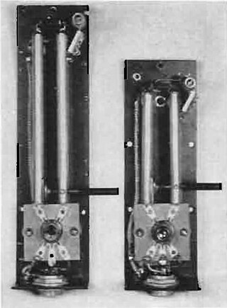
A mechanical filter is a signal processing filter usually used in place of an electronic filter at radio frequencies. Its purpose is the same as that of a normal electronic filter: to pass a range of signal frequencies, but to block others. The filter acts on mechanical vibrations which are the analogue of the electrical signal. At the input and output of the filter, transducers convert the electrical signal into, and then back from, these mechanical vibrations.

Commensurate line circuits are electrical circuits composed of transmission lines that are all the same length; commonly one-eighth of a wavelength. Lumped element circuits can be directly converted to distributed-element circuits of this form by the use of Richards' transformation. This transformation has a particularly simple result; inductors are replaced with transmission lines terminated in short-circuits and capacitors are replaced with lines terminated in open-circuits. Commensurate line theory is particularly useful for designing distributed-element filters for use at microwave frequencies.
The impedance analogy is a method of representing a mechanical system by an analogous electrical system. The advantage of doing this is that there is a large body of theory and analysis techniques concerning complex electrical systems, especially in the field of filters. By converting to an electrical representation, these tools in the electrical domain can be directly applied to a mechanical system without modification. A further advantage occurs in electromechanical systems: Converting the mechanical part of such a system into the electrical domain allows the entire system to be analysed as a unified whole.
Mechanical–electrical analogies are the representation of mechanical systems as electrical networks. At first, such analogies were used in reverse to help explain electrical phenomena in familiar mechanical terms. James Clerk Maxwell introduced analogies of this sort in the 19th century. However, as electrical network analysis matured it was found that certain mechanical problems could more easily be solved through an electrical analogy. Theoretical developments in the electrical domain that were particularly useful were the representation of an electrical network as an abstract topological diagram using the lumped element model and the ability of network analysis to synthesise a network to meet a prescribed frequency function.
The mobility analogy, also called admittance analogy or Firestone analogy, is a method of representing a mechanical system by an analogous electrical system. The advantage of doing this is that there is a large body of theory and analysis techniques concerning complex electrical systems, especially in the field of filters. By converting to an electrical representation, these tools in the electrical domain can be directly applied to a mechanical system without modification. A further advantage occurs in electromechanical systems: Converting the mechanical part of such a system into the electrical domain allows the entire system to be analysed as a unified whole.
