Related Research Articles

A lathe is a machine tool that rotates a workpiece about an axis of rotation to perform various operations such as cutting, sanding, knurling, drilling, deformation, facing, and turning, with tools that are applied to the workpiece to create an object with symmetry about that axis.

Computer-aided manufacturing (CAM) also known as computer-aided modeling or computer-aided machining is the use of software to control machine tools in the manufacturing of work pieces. This is not the only definition for CAM, but it is the most common. It may also refer to the use of a computer to assist in all operations of a manufacturing plant, including planning, management, transportation and storage. Its primary purpose is to create a faster production process and components and tooling with more precise dimensions and material consistency, which in some cases, uses only the required amount of raw material, while simultaneously reducing energy consumption. CAM is now a system used in schools and lower educational purposes. CAM is a subsequent computer-aided process after computer-aided design (CAD) and sometimes computer-aided engineering (CAE), as the model generated in CAD and verified in CAE can be input into CAM software, which then controls the machine tool. CAM is used in many schools alongside CAD to create objects.

Metalworking is the process of shaping and reshaping metals to create useful objects, parts, assemblies, and large scale structures. As a term it covers a wide and diverse range of processes, skills, and tools for producing objects on every scale: from huge ships, buildings, and bridges down to precise engine parts and delicate jewelry.
A machinist is a tradesperson or trained professional who operates machine tools, and has the ability to set up tools such as milling machines, grinders, lathes, and drilling machines.

Machining is a manufacturing process whereby a desired shape or part is achieved by the controlled removal of material from a larger piece of raw material by cutting; it is most often performed with metal material. These processes are collectively called subtractive manufacturing, which utilizes machine tools, in contrast to additive manufacturing, which uses controlled addition of material.
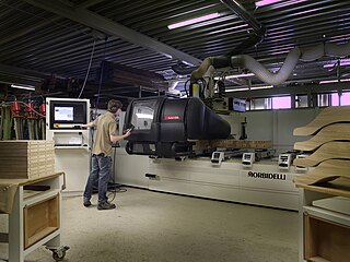
In machining, numerical control, also called computer numerical control (CNC), is the automated control of tools by means of a computer. It is used to operate tools such as drills, lathes, mills, grinders, routers and 3D printers. CNC transforms a piece of material into a specified shape by following coded programmed instructions and without a manual operator directly controlling the machining operation.
A reamer is a type of rotary cutting tool used in metalworking. Precision reamers are designed to enlarge the size of a previously formed hole by a small amount but with a high degree of accuracy to leave smooth sides. There are also non-precision reamers which are used for more basic enlargement of holes or for removing burrs. The process of enlarging the hole is called reaming. There are many different types of reamer and they may be designed for use as a hand tool or in a machine tool, such as a milling machine or drill press.
G-code is the most widely used computer numerical control (CNC) and 3D printing programming language. It is used mainly in computer-aided manufacturing to control automated machine tools, as well as for 3D-printer slicer applications. The G stands for geometry. G-code has many variants.
Diamond turning is turning using a cutting tool with a diamond tip. It is a process of mechanical machining of precision elements using lathes or derivative machine tools equipped with natural or synthetic diamond-tipped tool bits. The term single-point diamond turning (SPDT) is sometimes applied, although as with other lathe work, the "single-point" label is sometimes only nominal. The process of diamond turning is widely used to manufacture high-quality aspheric optical elements from crystals, metals, acrylic, and other materials. Plastic optics are frequently molded using diamond turned mold inserts. Optical elements produced by the means of diamond turning are used in optical assemblies in telescopes, video projectors, missile guidance systems, lasers, scientific research instruments, and numerous other systems and devices. Most SPDT today is done with computer numerical control (CNC) machine tools. Diamonds also serve in other machining processes, such as milling, grinding, and honing. Diamond turned surfaces have a high specular brightness and require no additional polishing or buffing, unlike other conventionally machined surfaces.

The phrase speeds and feeds or feeds and speeds refers to two separate velocities in machine tool practice, cutting speed and feed rate. They are often considered as a pair because of their combined effect on the cutting process. Each, however, can also be considered and analyzed in its own right.

A Tool and Cutter Grinder is used to sharpen milling cutters and tool bits along with a host of other cutting tools.

Turning is a machining process in which a cutting tool, typically a non-rotary tool bit, describes a helix toolpath by moving more or less linearly while the workpiece rotates.
Milling cutters are cutting tools typically used in milling machines or machining centres to perform milling operations. They remove material by their movement within the machine or directly from the cutter's shape.
In machining, a metal lathe or metalworking lathe is a large class of lathes designed for precisely machining relatively hard materials. They were originally designed to machine metals; however, with the advent of plastics and other materials, and with their inherent versatility, they are used in a wide range of applications, and a broad range of materials. In machining jargon, where the larger context is already understood, they are usually simply called lathes, or else referred to by more-specific subtype names. These rigid machine tools remove material from a rotating workpiece via the movements of various cutting tools, such as tool bits and drill bits.
In manufacturing, threading is the process of creating a screw thread. More screw threads are produced each year than any other machine element. There are many methods of generating threads, including subtractive methods ; deformative or transformative methods ; additive methods ; or combinations thereof.
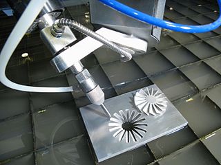
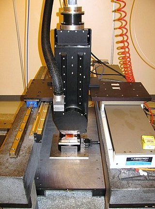
Multiaxis machining is a manufacturing process that involves tools that move in 4 or more directions and are used to manufacture parts out of metal or other materials by milling away excess material, by water jet cutting or by laser cutting. This type of machining was originally performed mechanically on large complex machines. These machines operated on 4, 5, 6, and even 12 axes which were controlled individually via levers that rested on cam plates. The cam plates offered the ability to control the tooling device, the table in which the part is secured, as well as rotating the tooling or part within the machine. Due to the machines size and complexity it took extensive amounts of time to set them up for production. Once computer numerically controlled machining was introduced it provided a faster, more efficient method for machining complex parts.
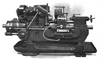
In metalworking and woodworking, an automatic lathe is a lathe with an automatically controlled cutting process. Automatic lathes were first developed in the 1870s and were mechanically controlled. From the advent of NC and CNC in the 1950s, the term automatic lathe has generally been used for only mechanically controlled lathes, although some manufacturers market Swiss-type CNC lathes as 'automatic'.

Milling is the process of machining using rotary cutters to remove material by advancing a cutter into a workpiece. This may be done by varying directions on one or several axes, cutter head speed, and pressure. Milling covers a wide variety of different operations and machines, on scales from small individual parts to large, heavy-duty gang milling operations. It is one of the most commonly used processes for machining custom parts to precise tolerances.
A canned cycle is a way of conveniently performing repetitive CNC machine operations. Canned cycles automate certain machining functions such as drilling, boring, threading, pocketing, etc... Canned cycles are so called because they allow a concise way to program a machine to produce a feature of a part. A canned cycle is also known as a fixed cycle. A canned cycle is usually permanently stored as a pre-program in the machine's controller and cannot be altered by the user.
References
- ↑ Virasak, LamNgeun. Manufacturing Processes 4-5. Open Oregon Educational Resources. p. 21. ISBN 978-1-63635-048-6.