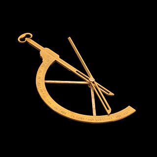
A position circle is a circle that can be measured both from a chart and from the surface of the earth for the purpose of position fixing. For the purposes of land or coastal navigation, a position circle can be generated by making a horizontal angle measurement between two landmarks using a sextant. Two overlapping position circles, or one position circle and one or more other observations can be used to give a position fix.
When a horizontal angle measurement is made between two known points on land, the observer will be located at the apex of a triangle, with the other two corners of this triangle consisting of the landmark pair. The observer will also be sitting on a set of points that fall along a large circle. The diameter of the circle will be dependent upon the distance between the landmark pair and the range of the observer to the landmark pair. At each point along this circle, the angular separation between the landmark pairs will be the same. Two such circles exist, one in front of the landmark pair, and one on the backside. It is usually straightforward to tell which circle is relevant. After the observation is made, the angular reading can be transferred onto a nautical chart (or map) by means of a protractor instrument. [1]
The origin of the circle can be found as follows. Draw a baseline connecting the two landmarks. Bisect the line using a compass. Construct a line 90 degrees to the baseline using a compass. Using a protractor, draw a line from either landmark to intersect the 90 degree line off the baseline at the observed angle. This point is the origin of the circle of position. Using a compass again, the entire circle can be drawn.

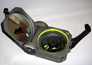
A sextant is a doubly reflecting navigation instrument that measures the angular distance between two visible objects. The primary use of a sextant is to measure the angle between an astronomical object and the horizon for the purposes of celestial navigation.

A compass is a device that shows the cardinal directions used for navigation and geographic orientation. It commonly consists of a magnetized needle or other element, such as a compass card or compass rose, which can pivot to align itself with magnetic north. Other methods may be used, including gyroscopes, magnetometers, and GPS receivers.

Surveying or land surveying is the technique, profession, art, and science of determining the terrestrial two-dimensional or three-dimensional positions of points and the distances and angles between them. These points are usually on the surface of the Earth, and they are often used to establish maps and boundaries for ownership, locations, such as the designed positions of structural components for construction or the surface location of subsurface features, or other purposes required by government or civil law, such as property sales.

Celestial navigation, also known as astronavigation, is the practice of position fixing using stars and other celestial bodies that enables a navigator to accurately determine their actual current physical position in space or on the surface of the Earth without relying solely on estimated positional calculations, commonly known as dead reckoning. Celestial navigation is performed without using satellite navigation or other similar modern electronic or digital positioning means.
In navigation, bearing or azimuth is the horizontal angle between the direction of an object and north or another object. The angle value can be specified in various angular units, such as degrees, mils, or grad. More specifically:
The term “set and drift” is used to describe external forces that affect a boat and keep it from following an intended course. To understand and calculate set and drift, one needs to first understand currents. Ocean currents are the horizontal movements of water from one location to another. The movement of water is impacted by: meteorological effects, wind, temperature differences, gravity, and on occasion earthquakes. Set is referred to as the current's direction, expressed in true degrees. Drift is referred to as the current's speed, which is usually measured in knots. “Leeway” refers to the amount of sidewards translation of a vessel drifting off of or away from the intended course of travel

A theodolite is a precision optical instrument for measuring angles between designated visible points in the horizontal and vertical planes. The traditional use has been for land surveying, but it is also used extensively for building and infrastructure construction, and some specialized applications such as meteorology and rocket launching.
Piloting or pilotage is the process of navigating on water or in the air using fixed points of reference on the sea or on land, usually with reference to a nautical chart or aeronautical chart to obtain a fix of the position of the vessel or aircraft with respect to a desired course or location. Horizontal fixes of position from known reference points may be obtained by sight or by radar. Vertical position may be obtained by depth sounder to determine depth of the water body below a vessel or by altimeter to determine an aircraft's altitude, from which its distance above the ground can be deduced. Piloting a vessel is usually practiced close to shore or on inland waterways. Pilotage of an aircraft is practiced under visual meteorological conditions for flight.
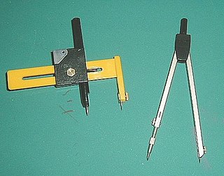
A compass, more accurately known as a pair of compasses, is a technical drawing instrument that can be used for inscribing circles or arcs. As dividers, it can also be used as a tool to mark out distances, in particular, on maps. Compasses can be used for mathematics, drafting, navigation and other purposes.
A goniometer is an instrument that either measures an angle or allows an object to be rotated to a precise angular position. The term goniometry derives from two Greek words, γωνία (gōnía) 'angle' and μέτρον (métron) 'measure'. The protractor is a commonly used type in the fields of mechanics, engineering, and geometry.

A milliradian is an SI derived unit for angular measurement which is defined as a thousandth of a radian (0.001 radian). Milliradians are used in adjustment of firearm sights by adjusting the angle of the sight compared to the barrel. Milliradians are also used for comparing shot groupings, or to compare the difficulty of hitting different sized shooting targets at different distances. When using a scope with both mrad adjustment and a reticle with mrad markings, the shooter can use the reticle as a ruler to count the number of mrads a shot was off-target, which directly translates to the sight adjustment needed to hit the target with a follow-up shot. Optics with mrad markings in the reticle can also be used to make a range estimation of a known size target, or vice versa, to determine a target size if the distance is known, a practice called "milling".
Navigational instruments are instruments used by nautical navigators and pilots as tools of their trade. The purpose of navigation is to ascertain the present position and to determine the speed, direction, etc. to arrive at the port or point of destination.

A set square or triangle is an object used in engineering and technical drawing, with the aim of providing a straightedge at a right angle or other particular planar angle to a baseline.
In astronomical navigation, the intercept method, also known as Marcq St. Hilaire method, is a method of calculating an observer's position on Earth (geopositioning). It was originally called the azimuth intercept method because the process involves drawing a line which intercepts the azimuth line. This name was shortened to intercept method and the intercept distance was shortened to 'intercept'.

Diver navigation, termed "underwater navigation" by scuba divers, is a set of techniques—including observing natural features, the use of a compass, and surface observations—that divers use to navigate underwater. Free-divers do not spend enough time underwater for navigation to be important, and surface supplied divers are limited in the distance they can travel by the length of their umbilicals and are usually directed from the surface control point. On those occasions when they need to navigate they can use the same methods used by scuba divers.
Reflecting instruments are those that use mirrors to enhance their ability to make measurements. In particular, the use of mirrors permits one to observe two objects simultaneously while measuring the angular distance between the objects. While reflecting instruments are used in many professions, they are primarily associated with celestial navigation as the need to solve navigation problems, in particular the problem of the longitude, was the primary motivation in their development.
Position resection and intersection are methods for determining an unknown geographic position by measuring angles with respect to known positions. In resection, the one point with unknown coordinates is occupied and sightings are taken to the known points; in intersection, the two points with known coordinates are occupied and sightings are taken to the unknown point.

Drafting tools may be used for measurement and layout of drawings, or to improve the consistency and speed of creation of standard drawing elements. Tools such as pens and pencils mark the drawing medium. Other tools such as straight edges, assist the operator in drawing straight lines, or assist the operator in drawing complicated shapes repeatedly. Various scales and the protractor are used to measure the lengths of lines and angles, allowing accurate scale drawing to be carried out. The compass is used to draw arcs and circles. A drawing board was used to hold the drawing media in place; later boards included drafting machines that sped the layout of straight lines and angles. Tools such as templates and lettering guides assisted in the drawing of repetitive elements such as circles, ellipses, schematic symbols and text. Other auxiliary tools were used for special drawing purposes or for functions related to the preparation and revision of drawings. The tools used for manual technical drawing have been displaced by the advent of computer-aided drawing, drafting and design (CADD).
A schema for horizontal dials is a set of instructions used to construct horizontal sundials using compass and straightedge construction techniques, which were widely used in Europe from the late fifteenth century to the late nineteenth century. The common horizontal sundial is a geometric projection of an equatorial sundial onto a horizontal plane.

Vertical declining dials are sundials that indicate local apparent time. Vertical south dials are a special case: as are vertical north, vertical east and vertical west dials. The word declining means that the wall is offset from one of these 4 cardinal points. There are dials that are not vertical, and these are called reclining dials.
| | This cartography or mapping term article is a stub. You can help Wikipedia by expanding it. |