The compression ratio is the ratio between the volume of the cylinder and combustion chamber in an internal combustion engine at their maximum and minimum values.

In an internal combustion engine, a turbocharger is a forced induction device that is powered by the flow of exhaust gases. It uses this energy to compress the intake gas, forcing more air into the engine in order to produce more power for a given displacement.
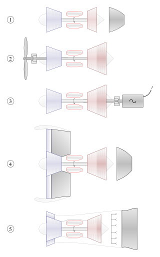
A gas turbine, also called a combustion turbine, is a type of continuous flow internal combustion engine. The main parts common to all gas turbine engines form the power-producing part and are, in the direction of flow:

In engineering, the Miller cycle is a thermodynamic cycle used in a type of internal combustion engine. The Miller cycle was patented by Ralph Miller, an American engineer, U.S. Patent 2,817,322 dated Dec 24, 1957. The engine may be two- or four-stroke and may be run on diesel fuel, gases, or dual fuel.
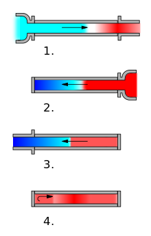
A four-strokeengine is an internal combustion (IC) engine in which the piston completes four separate strokes while turning the crankshaft. A stroke refers to the full travel of the piston along the cylinder, in either direction. The four separate strokes are termed:
- Intake: Also known as induction or suction. This stroke of the piston begins at top dead center (T.D.C.) and ends at bottom dead center (B.D.C.). In this stroke the intake valve must be in the open position while the piston pulls an air-fuel mixture into the cylinder by producing vacuum pressure into the cylinder through its downward motion. The piston is moving down as air is being sucked in by the downward motion against the piston.
- Compression: This stroke begins at B.D.C, or just at the end of the suction stroke, and ends at T.D.C. In this stroke the piston compresses the air-fuel mixture in preparation for ignition during the power stroke (below). Both the intake and exhaust valves are closed during this stage.
- Combustion: Also known as power or ignition. This is the start of the second revolution of the four stroke cycle. At this point the crankshaft has completed a full 360 degree revolution. While the piston is at T.D.C. the compressed air-fuel mixture is ignited by a spark plug or by heat generated by high compression, forcefully returning the piston to B.D.C. This stroke produces mechanical work from the engine to turn the crankshaft.
- Exhaust: Also known as outlet. During the exhaust stroke, the piston, once again, returns from B.D.C. to T.D.C. while the exhaust valve is open. This action expels the spent air-fuel mixture through the exhaust valve.

The turbojet is an airbreathing jet engine which is typically used in aircraft. It consists of a gas turbine with a propelling nozzle. The gas turbine has an air inlet which includes inlet guide vanes, a compressor, a combustion chamber, and a turbine. The compressed air from the compressor is heated by burning fuel in the combustion chamber and then allowed to expand through the turbine. The turbine exhaust is then expanded in the propelling nozzle where it is accelerated to high speed to provide thrust. Two engineers, Frank Whittle in the United Kingdom and Hans von Ohain in Germany, developed the concept independently into practical engines during the late 1930s.

The Roots-type blower is a positive displacement lobe pump which operates by pumping a fluid with a pair of meshing lobes resembling a set of stretched gears. Fluid is trapped in pockets surrounding the lobes and carried from the intake side to the exhaust. The most common application of the Roots-type blower has been the induction device on two-stroke diesel engines, such as those produced by Detroit Diesel and Electro-Motive Diesel. Roots-type blowers are also used to supercharge four-stroke Otto cycle engines, with the blower being driven from the engine's crankshaft via a toothed or V-belt, a roller chain or a gear train.
The Brayton cycle is a thermodynamic cycle that describes the operation of certain heat engines that have air or some other gas as their working fluid. The original Brayton engines used a piston compressor and piston expander, but modern gas turbine engines and airbreathing jet engines also follow the Brayton cycle. Although the cycle is usually run as an open system, it is conventionally assumed for the purposes of thermodynamic analysis that the exhaust gases are reused in the intake, enabling analysis as a closed system.

In an internal combustion engine, forced induction is where turbocharging or supercharging is used to increase the density of the intake air. Engines without forced induction are classified as naturally aspirated.

Turbomachinery, in mechanical engineering, describes machines that transfer energy between a rotor and a fluid, including both turbines and compressors. While a turbine transfers energy from a fluid to a rotor, a compressor transfers energy from a rotor to a fluid.
A twincharger refers to a compound forced induction system used on some internal combustion engines. It is a combination of an exhaust-driven turbocharger and a mechanically driven supercharger, each mitigating the weaknesses of the other.
Twin-turbo refers to an engine in which two turbochargers work in tandem to compress the intake fuel/air mixture. The most common layout features two identical or mirrored turbochargers in parallel, each processing half of a V engine's produced exhaust through independent piping. The two turbochargers can either be matching or different sizes.
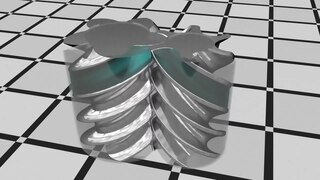
A rotary-screw compressor is a type of gas compressor, such as an air compressor, that uses a rotary-type positive-displacement mechanism. These compressors are common in industrial applications and replace more traditional piston compressors where larger volumes of compressed gas are needed, e.g. for large refrigeration cycles such as chillers, or for compressed air systems to operate air-driven tools such as jackhammers and impact wrenches. For smaller rotor sizes the inherent leakage in the rotors becomes much more significant, leading to this type of mechanism being less suitable for smaller compressors than piston compressors.

In an internal combustion engine, a supercharger compresses the intake gas, forcing more air into the engine in order to produce more power for a given displacement.

A two-stroke diesel engine is an internal combustion engine that uses compression ignition, with a two-stroke combustion cycle. It was invented by Hugo Güldner in 1899.
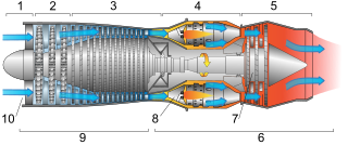
This article briefly describes the components and systems found in jet engines.
An airbreathing jet engine is a jet engine that ejects a propelling (reaction) jet of hot exhaust gases after first taking in atmospheric air, followed by compression, heating and expansion back to atmospheric pressure through a nozzle. Alternatively the reaction jet may include a cold jet of ducted bypass air which has been compressed by a fan before returning to atmospheric pressure through an additional nozzle. These engines are gas turbine engines. Engines using only ram for the compression process, and no turbomachinery, are the ramjet and pulsejet.
Internal combustion engines come in a wide variety of types, but have certain family resemblances, and thus share many common types of components.

An internal combustion engine is a heat engine in which the combustion of a fuel occurs with an oxidizer in a combustion chamber that is an integral part of the working fluid flow circuit. In an internal combustion engine, the expansion of the high-temperature and high-pressure gases produced by combustion applies direct force to some component of the engine. The force is typically applied to pistons, turbine blades, a rotor, or a nozzle. This force moves the component over a distance, transforming chemical energy into kinetic energy which is used to propel, move or power whatever the engine is attached to. This replaced the external combustion engine for applications where the weight or size of an engine was more important.
Wankel Diesel engine describes the idea of using the Diesel principle in a Wankel rotary engine. Several attempts to build such an engine have been made by different engineers and manufacturers in the 1960s and 1970s. Due to technical problems and the general disadvantages of the Wankel design, the Wankel Diesel engine never left the prototype stage, and designing a Wankel Diesel engine capable of running under its own power is thus considered unfeasible.