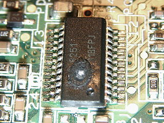
In electronics, the metal–oxide–semiconductor field-effect transistor is a type of field-effect transistor (FET), most commonly fabricated by the controlled oxidation of silicon. It has an insulated gate, the voltage of which determines the conductivity of the device. This ability to change conductivity with the amount of applied voltage can be used for amplifying or switching electronic signals. The term metal–insulator–semiconductor field-effect transistor (MISFET) is almost synonymous with MOSFET. Another near-synonym is insulated-gate field-effect transistor (IGFET).
In electrical engineering, partial discharge (PD) is a localized dielectric breakdown (DB) of a small portion of a solid or fluid electrical insulation (EI) system under high voltage (HV) stress. While a corona discharge (CD) is usually revealed by a relatively steady glow or brush discharge (BD) in air, partial discharges within solid insulation system are not visible.

A Lichtenberg figure, or Lichtenberg dust figure, is a branching electric discharge that sometimes appears on the surface or in the interior of insulating materials. Lichtenberg figures are often associated with the progressive deterioration of high-voltage components and equipment. The study of planar Lichtenberg figures along insulating surfaces and 3D electrical trees within insulating materials often provides engineers with valuable insights for improving the long-term reliability of high-voltage equipment. Lichtenberg figures are now known to occur on or within solids, liquids, and gases during electrical breakdown.

In electronics, electrical breakdown or dielectric breakdown is a process that occurs when an electrically insulating material, subjected to a high enough voltage, suddenly becomes a conductor and current flows through it. All insulating materials undergo breakdown when the electric field caused by an applied voltage exceeds the material's dielectric strength. The voltage at which a given insulating object becomes conductive is called its breakdown voltage and, in addition to its dielectric strength, depends on its size and shape, and the location on the object at which the voltage is applied. Under sufficient voltage, electrical breakdown can occur within solids, liquids, or gases. However, the specific breakdown mechanisms are different for each kind of dielectric medium.

The breakdown voltage of an insulator is the minimum voltage that causes a portion of an insulator to experience electrical breakdown and become electrically conductive.
In the semiconductor industry, the term high-κ dielectric refers to a material with a high dielectric constant, as compared to silicon dioxide. High-κ dielectrics are used in semiconductor manufacturing processes where they are usually used to replace a silicon dioxide gate dielectric or another dielectric layer of a device. The implementation of high-κ gate dielectrics is one of several strategies developed to allow further miniaturization of microelectronic components, colloquially referred to as extending Moore's Law.

Capacitors are manufactured in many styles, forms, dimensions, and from a large variety of materials. They all contain at least two electrical conductors, called plates, separated by an insulating layer (dielectric). Capacitors are widely used as parts of electrical circuits in many common electrical devices.

The Pearson–Anson effect, discovered in 1922 by Stephen Oswald Pearson and Horatio Saint George Anson, is the phenomenon of an oscillating electric voltage produced by a neon bulb connected across a capacitor, when a direct current is applied through a resistor. This circuit, now called the Pearson-Anson oscillator, neon lamp oscillator, or sawtooth oscillator, is one of the simplest types of relaxation oscillator. It generates a sawtooth output waveform. It has been used in low frequency applications such as blinking warning lights, stroboscopes, tone generators in electronic organs and other electronic music circuits, and in time base generators and deflection circuits of early cathode-ray tube oscilloscopes. Since the development of microelectronics, these simple negative resistance oscillators have been superseded in many applications by more flexible semiconductor relaxation oscillators such as the 555 timer IC.

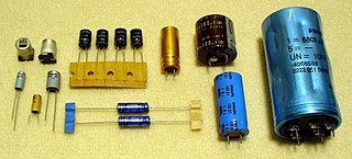
In electrical engineering, a capacitor is a device that stores electrical energy by accumulating electric charges on two closely spaced surfaces that are insulated from each other. The capacitor was originally known as the condenser, a term still encountered in a few compound names, such as the condenser microphone. It is a passive electronic component with two terminals.
Negative-bias temperature instability (NBTI) is a key reliability issue in MOSFETs, a type of transistor aging. NBTI manifests as an increase in the threshold voltage and consequent decrease in drain current and transconductance of a MOSFET. The degradation is often approximated by a power-law dependence on time. It is of immediate concern in p-channel MOS devices (pMOS), since they almost always operate with negative gate-to-source voltage; however, the very same mechanism also affects nMOS transistors when biased in the accumulation regime, i.e. with a negative bias applied to the gate.
Hot carrier injection (HCI) is a phenomenon in solid-state electronic devices where an electron or a “hole” gains sufficient kinetic energy to overcome a potential barrier necessary to break an interface state. The term "hot" refers to the effective temperature used to model carrier density, not to the overall temperature of the device. Since the charge carriers can become trapped in the gate dielectric of a MOS transistor, the switching characteristics of the transistor can be permanently changed. Hot-carrier injection is one of the mechanisms that adversely affects the reliability of semiconductors of solid-state devices.

A gate dielectric is a dielectric used between the gate and substrate of a field-effect transistor. In state-of-the-art processes, the gate dielectric is subject to many constraints, including:

The antenna effect, more formally plasma induced gate oxide damage, is an effect that can potentially cause yield and reliability problems during the manufacture of MOS integrated circuits. Factories (fabs) normally supply antenna rules, which are rules that must be obeyed to avoid this problem. A violation of such rules is called an antenna violation. The word antenna is something of a misnomer in this context—the problem is really the collection of charge, not the normal meaning of antenna, which is a device for converting electromagnetic fields to/from electrical currents. Occasionally the phrase antenna effect is used in this context, but this is less common since there are many effects, and the phrase does not make clear which is meant.
Time-dependent gate oxide breakdown is a kind of transistor aging, a failure mechanism in MOSFETs, when the gate oxide breaks down as a result of long-time application of relatively low electric field. The breakdown is caused by formation of a conducting path through the gate oxide to substrate due to electron tunneling current, when MOSFETs are operated close to or beyond their specified operating voltages.

A tantalum electrolytic capacitor is an electrolytic capacitor, a passive component of electronic circuits. It consists of a pellet of porous tantalum metal as an anode, covered by an insulating oxide layer that forms the dielectric, surrounded by liquid or solid electrolyte as a cathode. The tantalum capacitor, because of its very thin and relatively high permittivity dielectric layer, distinguishes itself from other conventional and electrolytic capacitors in having high capacitance per volume and lower weight.
In electronics, leakage is the gradual transfer of electrical energy across a boundary normally viewed as insulating, such as the spontaneous discharge of a charged capacitor, magnetic coupling of a transformer with other components, or flow of current across a transistor in the "off" state or a reverse-polarized diode.

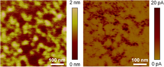
In microscopy, conductive atomic force microscopy (C-AFM) or current sensing atomic force microscopy (CS-AFM) is a mode in atomic force microscopy (AFM) that simultaneously measures the topography of a material and the electric current flow at the contact point of the tip with the surface of the sample. The topography is measured by detecting the deflection of the cantilever using an optical system, while the current is detected using a current-to-voltage preamplifier. The fact that the CAFM uses two different detection systems is a strong advantage compared to scanning tunneling microscopy (STM). Basically, in STM the topography picture is constructed based on the current flowing between the tip and the sample. Therefore, when a portion of a sample is scanned with an STM, it is not possible to discern if the current fluctuations are related to a change in the topography or to a change in the sample conductivity.

Electronic components have a wide range of failure modes. These can be classified in various ways, such as by time or cause. Failures can be caused by excess temperature, excess current or voltage, ionizing radiation, mechanical shock, stress or impact, and many other causes. In semiconductor devices, problems in the device package may cause failures due to contamination, mechanical stress of the device, or open or short circuits.
Transformer oil, a type of insulating and cooling oil used in transformers and other electrical equipment, needs to be tested periodically to ensure that it is still fit for purpose. This is because it tends to deteriorate over time. Testing sequences and procedures are defined by various international standards, many of them set by ASTM. Transformer oil testing consists of measuring breakdown voltage and other physical and chemical properties of samples of the oil, either in a laboratory or using portable test equipment on-site.

Aluminium electrolytic capacitors are (usually) polarized electrolytic capacitors whose anode electrode (+) is made of a pure aluminium foil with an etched surface. The aluminum forms a very thin insulating layer of aluminium oxide by anodization that acts as the dielectric of the capacitor. A non-solid electrolyte covers the rough surface of the oxide layer, serving in principle as the second electrode (cathode) (-) of the capacitor. A second aluminum foil called "cathode foil" contacts the electrolyte and serves as the electrical connection to the negative terminal of the capacitor.


