Ripple tank

Last updated
A simple ripple tank Simple ripple tank.svg
A simple ripple tank

In physics, a ripple tank is a shallow glass tank of water used to demonstrate the basic properties of waves. It is a specialized form of a wave tank. The ripple tank is usually illuminated from above, so that the light shines through the water. Some small ripple tanks fit onto the top of an overhead projector, i.e. they are illuminated from below. The ripples on the water show up as shadows on the screen underneath the tank. All the basic properties of waves, including reflection, refraction, interference and diffraction, can be demonstrated.

Contents

Ripples may be generated by a piece of wood that is suspended above the tank on elastic bands so that it is just touching the surface. Screwed to wood is a motor that has an off center weight attached to the axle. As the axle rotates the motor wobbles, shaking the wood and generating ripples.

Demonstrating wave properties

A number of wave properties can be demonstrated with a ripple tank. These include plane waves, reflection, refraction, interference and diffraction.

Plane waves

Image of plane waves Ripple tank plane waves.png
Image of plane waves

When the rippler is lowered so that it just touches the surface of the water, plane waves will be produced.

Circular waves

Ripple tank with a spherical source producing circular waves Rippletanksource2.gif
Ripple tank with a spherical source producing circular waves

When the rippler is attached with a point spherical ball and lowered so that it just touches the surface of the water, circular waves will be produced.

Reflection

Waves that are long relative to the size of an object will wrap around the object. Diffraction with large object.png
Waves that are long relative to the size of an object will wrap around the object.
Waves that are short in respect to the size of an object will cast a shadow behind the object. Diffraction of a large object in short waves.png
Waves that are short in respect to the size of an object will cast a shadow behind the object.
Numerical approximation of diffraction pattern from a slit of width equal to five times the wavelength of an incident plane wave in 3D visualization 5wavelength=slitwidthsprectrum.gif
Numerical approximation of diffraction pattern from a slit of width equal to five times the wavelength of an incident plane wave in 3D visualization
Numerical approximation of diffraction pattern from a slit of width equal to wavelength of an incident plane wave in 3D visualization Wavelength=slitwidthspectrum.gif
Numerical approximation of diffraction pattern from a slit of width equal to wavelength of an incident plane wave in 3D visualization

Demonstrating reflection and focusing of mirrors

By placing a metal bar in the tank and tapping the wooden bar a pulse of three or four ripples can be sent towards the metal bar. The ripples reflect from the bar. If the bar is placed at an angle to the wavefront the reflected waves can be seen to obey the law of reflection. The angle of incidence and angle of reflection will be the same.

If a concave parabolic obstacle is used, a plane wave pulse will converge on a point after reflection. This point is the focal point of the mirror. Circular waves can be produced by dropping a single drop of water into the ripple tank. If this is done at the focal point of the "mirror" plane waves will be reflected back.

Refraction

If a sheet of glass is placed in the tank, the depth of water in the tank will be shallower over the glass than elsewhere. The speed of a wave in water depends on the depth, so the ripples slow down as they pass over the glass. This causes the wavelength to decrease. If the junction between the deep and shallow water is at an angle to the wavefront, the waves will refract. In the diagram above, the waves can be seen to bend towards the normal. The normal is shown as a dotted line. The dashed line is the direction that the waves would travel if they had not met the angled piece of glass.

In practice, showing refraction with a ripple tank is quite tricky to do.

Diffraction

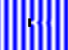
If a small obstacle is placed in the path of the ripples, and a slow frequency is used, there is no shadow area as the ripples refract around it, as shown below on the right. A faster frequency may result in a shadow, as shown below on the right. If a large obstacle is placed in the tank, a shadow area will probably be observed.

If an obstacle with a small gap is placed in the tank the ripples emerge in an almost semicircular pattern. If the gap is large however, the diffraction is much more limited. Small, in this context, means that the size of the obstacle is comparable to the wavelength of the ripples.

Diffraction from a grid

A phenomenon identical to the x-ray diffraction of x-rays from an atomic crystal lattice can also be seen, thus demonstrating the principles of crystallography. If one lowers a grid of obstacles into the water, with the spacing between the obstacles roughly corresponding to the wavelength of the water waves, one will see diffraction from the grid. At certain angles between the grid and the oncoming waves, the waves will appear to reflect off the grid; at other angles, the waves will pass through. Similarly, if the frequency (wavelength) of the waves is altered, the waves will also alternately pass through or be reflected, depending on the precise relationship between spacing, orientation and wavelength.

Interference

Interference can be produced by the use of two dippers that are attached to the main ripple bar. In the diagrams below on the left the light areas represent crests of waves, the black areas represent troughs. Notice the grey areas: they are areas of destructive interference where the waves from the two sources cancel one another out. To the right is a photograph of two-point interference generated in a circular ripple tank.

See also

Related Research Articles

<span class="mw-page-title-main">Augustin-Jean Fresnel</span> French optical physicist (1788–1827)

Augustin-Jean Fresnel was a French civil engineer and physicist whose research in optics led to the almost unanimous acceptance of the wave theory of light, excluding any remnant of Newton's corpuscular theory, from the late 1830s  until the end of the 19th century. He is perhaps better known for inventing the catadioptric (reflective/refractive) Fresnel lens and for pioneering the use of "stepped" lenses to extend the visibility of lighthouses, saving countless lives at sea. The simpler dioptric stepped lens, first proposed by Count Buffon  and independently reinvented by Fresnel, is used in screen magnifiers and in condenser lenses for overhead projectors.

<span class="mw-page-title-main">Diffraction</span> Phenomenon of the motion of waves

Diffraction is the interference or bending of waves around the corners of an obstacle or through an aperture into the region of geometrical shadow of the obstacle/aperture. The diffracting object or aperture effectively becomes a secondary source of the propagating wave. Italian scientist Francesco Maria Grimaldi coined the word diffraction and was the first to record accurate observations of the phenomenon in 1660.

<span class="mw-page-title-main">Optics</span> Branch of physics that studies light

Optics is the branch of physics that studies the behaviour and properties of light, including its interactions with matter and the construction of instruments that use or detect it. Optics usually describes the behaviour of visible, ultraviolet, and infrared light. Because light is an electromagnetic wave, other forms of electromagnetic radiation such as X-rays, microwaves, and radio waves exhibit similar properties.

<span class="mw-page-title-main">Refraction</span> Physical phenomenon relating to the direction of waves

In physics, refraction is the redirection of a wave as it passes from one medium to another. The redirection can be caused by the wave's change in speed or by a change in the medium. Refraction of light is the most commonly observed phenomenon, but other waves such as sound waves and water waves also experience refraction. How much a wave is refracted is determined by the change in wave speed and the initial direction of wave propagation relative to the direction of change in speed.

<span class="mw-page-title-main">Total internal reflection</span> Reflection of a wave from a boundary between two media (rather than refraction)

In physics, total internal reflection (TIR) is the phenomenon in which waves arriving at the interface (boundary) from one medium to another are not refracted into the second ("external") medium, but completely reflected back into the first ("internal") medium. It occurs when the second medium has a higher wave speed than the first, and the waves are incident at a sufficiently oblique angle on the interface. For example, the water-to-air surface in a typical fish tank, when viewed obliquely from below, reflects the underwater scene like a mirror with no loss of brightness (Fig. 1).

<span class="mw-page-title-main">Wavelength</span> Distance over which a waves shape repeats

In physics and mathematics, wavelength or spatial period of a wave or periodic function is the distance over which the wave's shape repeats. In other words, it is the distance between consecutive corresponding points of the same phase on the wave, such as two adjacent crests, troughs, or zero crossings. Wavelength is a characteristic of both traveling waves and standing waves, as well as other spatial wave patterns. The inverse of the wavelength is called the spatial frequency. Wavelength is commonly designated by the Greek letter lambda (λ). The term "wavelength" is also sometimes applied to modulated waves, and to the sinusoidal envelopes of modulated waves or waves formed by interference of several sinusoids.

<span class="mw-page-title-main">Wave</span> Repeated oscillation around equilibrium

In physics, mathematics, engineering, and related fields, a wave is a propagating dynamic disturbance of one or more quantities. Periodic waves oscillate repeatedly about an equilibrium (resting) value at some frequency. When the entire waveform moves in one direction, it is said to be a traveling wave; by contrast, a pair of superimposed periodic waves traveling in opposite directions makes a standing wave. In a standing wave, the amplitude of vibration has nulls at some positions where the wave amplitude appears smaller or even zero. Waves are often described by a wave equation or a one-way wave equation for single wave propagation in a defined direction.

<span class="mw-page-title-main">Diffraction grating</span> Optical component which splits light into several beams

In optics, a diffraction grating is an optical grating with a periodic structure that diffracts light into several beams traveling in different directions. The emerging coloration is a form of structural coloration. The directions or diffraction angles of these beams depend on the wave (light) incident angle to the diffraction grating, the spacing or distance between adjacent diffracting elements on the grating, and the wavelength of the incident light. The grating acts as a dispersive element. Because of this, diffraction gratings are commonly used in monochromators and spectrometers, but other applications are also possible such as optical encoders for high-precision motion control and wavefront measurement.

<span class="mw-page-title-main">Arago spot</span> Bright point that appears at the center of a circular objects shadow due to Fresnel diffraction.

In optics, the Arago spot, Poisson spot, or Fresnel spot is a bright point that appears at the center of a circular object's shadow due to Fresnel diffraction. This spot played an important role in the discovery of the wave nature of light and is a common way to demonstrate that light behaves as a wave.

<span class="mw-page-title-main">Holography</span> Recording to reproduce a three-dimensional light field

Holography is a technique that enables a wavefront to be recorded and later reconstructed. It is best known as a method of generating real three-dimensional images, but also has a wide range of other applications. In principle, it is possible to make a hologram for any type of wave.

In physics and chemistry, Bragg's law, Wulff–Bragg's condition or Laue–Bragg interference, a special case of Laue diffraction, gives the angles for coherent scattering of waves from a large crystal lattice. It encompasses the superposition of wave fronts scattered by lattice planes, leading to a strict relation between wavelength and scattering angle, or else to the wavevector transfer with respect to the crystal lattice. Such law had initially been formulated for X-rays upon crystals. However, it applies to all sorts of quantum beams, including neutron and electron waves at atomic distances if there are a large number of atoms, as well as visible light with artificial periodic microscale lattices.

<span class="mw-page-title-main">Reflection (physics)</span> "Bouncing back" of waves at an interface

Reflection is the change in direction of a wavefront at an interface between two different media so that the wavefront returns into the medium from which it originated. Common examples include the reflection of light, sound and water waves. The law of reflection says that for specular reflection the angle at which the wave is incident on the surface equals the angle at which it is reflected.

In optics, the Fraunhofer diffraction equation is used to model the diffraction of waves when plane waves are incident on a diffracting object, and the diffraction pattern is viewed at a sufficiently long distance from the object, and also when it is viewed at the focal plane of an imaging lens. In contrast, the diffraction pattern created near the diffracting object and is given by the Fresnel diffraction equation.

<span class="mw-page-title-main">Shearing interferometer</span>

The shearing interferometer is an extremely simple means to observe interference and to use this phenomenon to test the collimation of light beams, especially from laser sources which have a coherence length which is usually significantly longer than the thickness of the shear plate so that the basic condition for interference is fulfilled.

<span class="mw-page-title-main">Ray (optics)</span> Idealized model of light

In optics, a ray is an idealized geometrical model of light or other electromagnetic radiation, obtained by choosing a curve that is perpendicular to the wavefronts of the actual light, and that points in the direction of energy flow. Rays are used to model the propagation of light through an optical system, by dividing the real light field up into discrete rays that can be computationally propagated through the system by the techniques of ray tracing. This allows even very complex optical systems to be analyzed mathematically or simulated by computer. Ray tracing uses approximate solutions to Maxwell's equations that are valid as long as the light waves propagate through and around objects whose dimensions are much greater than the light's wavelength. Ray optics or geometrical optics does not describe phenomena such as diffraction, which require wave optics theory. Some wave phenomena such as interference can be modeled in limited circumstances by adding phase to the ray model.

X-ray optics is the branch of optics that manipulates X-rays instead of visible light. It deals with focusing and other ways of manipulating the X-ray beams for research techniques such as X-ray crystallography, X-ray fluorescence, small-angle X-ray scattering, X-ray microscopy, X-ray phase-contrast imaging, and X-ray astronomy.

Lloyd's mirror is an optics experiment that was first described in 1834 by Humphrey Lloyd in the Transactions of the Royal Irish Academy. Its original goal was to provide further evidence for the wave nature of light, beyond those provided by Thomas Young and Augustin-Jean Fresnel. In the experiment, light from a monochromatic slit source reflects from a glass surface at a small angle and appears to come from a virtual source as a result. The reflected light interferes with the direct light from the source, forming interference fringes. It is the optical wave analogue to a sea interferometer.

In physics, ray tracing is a method for calculating the path of waves or particles through a system with regions of varying propagation velocity, absorption characteristics, and reflecting surfaces. Under these circumstances, wavefronts may bend, change direction, or reflect off surfaces, complicating analysis. Ray tracing solves the problem by repeatedly advancing idealized narrow beams called rays through the medium by discrete amounts. Simple problems can be analyzed by propagating a few rays using simple mathematics. More detailed analysis can be performed by using a computer to propagate many rays.

<span class="mw-page-title-main">Thin-film interference</span> Optical phenomenon

Thin-film interference is a natural phenomenon in which light waves reflected by the upper and lower boundaries of a thin film interfere with one another, either enhancing or reducing the reflected light. When the thickness of the film is an odd multiple of one quarter-wavelength of the light on it, the reflected waves from both surfaces interfere to cancel each other. Since the wave cannot be reflected, it is completely transmitted instead. When the thickness is a multiple of a half-wavelength of the light, the two reflected waves reinforce each other, increasing the reflection and reducing the transmission. Thus when white light, which consists of a range of wavelengths, is incident on the film, certain wavelengths (colors) are intensified while others are attenuated. Thin-film interference explains the multiple colors seen in light reflected from soap bubbles and oil films on water. It is also the mechanism behind the action of antireflection coatings used on glasses and camera lenses. If the thickness of the film is much larger than the coherence length of the incident light, then the interference pattern will be washed out due to the linewidth of the light source.

Optical holography is a technique which enables an optical wavefront to be recorded and later re-constructed. Holography is best known as a method of generating three-dimensional images but it also has a wide range of other applications.

References